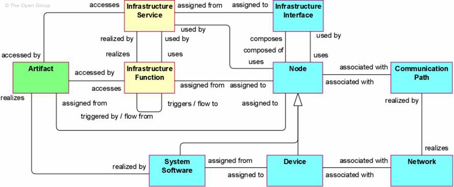
Figure 34 gives an overview of the technology layer concepts and their relationships. Many of the concepts have been inspired by the UML 2.0 standard [7], [10], as this is the dominant language and the de facto standard for describing software applications and infrastructure. Whenever applicable, we draw inspiration from the analogy with the business and application layers.
Figure 34: Technology Layer Metamodel
Note: This figure does not show all permitted relationships: every concept in the language can have composition, aggregation, and specialization relationships with concepts of the same type; furthermore, there are indirect relationships that can be derived as explained in Section 7.5.
The main active structure concept for the technology layer is the node. This concept is used to model structural entities in this layer. It is identical to the node concept of UML 2.0. It strictly models the structural aspect of a system: its behavior is modeled by an explicit relationship to the behavioral concepts.
An infrastructure interface is the (logical) location where the infrastructure services offered by a node can be accessed by other nodes or by application components from the application layer.
Nodes come in two flavors: device and system software, both taken from UML 2.0. A device models a physical computational resource, upon which artifacts may be deployed for execution. System software is an infrastructural software component running on a device. Typically, a node consists of a number of sub-nodes; for example, a device such as a server and system software to model the operating system.
The inter-relationships of components in the technology layer are mainly formed by the communication infrastructure. The communication path models the relation between two or more nodes, through which these nodes can exchange information. The physical realization of a communication path is a modeled with a network; i.e., a physical communication medium between two or more devices (or other networks).
A node is defined as a computational resource upon which artifacts may be stored or deployed for execution.
Nodes are active processing elements that execute and process artifacts, which are the representation of components and data objects. Nodes are, for example, used to model application servers, database servers, or client workstations. A node is often a combination of a hardware device and system software, thus providing a complete execution environment. These sub-nodes that represent the hardware devices and system software may be modeled explicitly or left implicit.
Nodes can be interconnected by communication paths. Artifacts can be assigned to (i.e., deployed on) nodes.
The name of a node should preferably be a noun. A node can consist of sub-nodes.
Artifacts deployed on a node may either be drawn inside the node or connected to it with an assignment relationship.
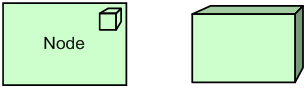
Figure 35: Node Notation
Example
In the model below, we see an Application Server node, which consists of a Blade device and Java EE-based application server system software.
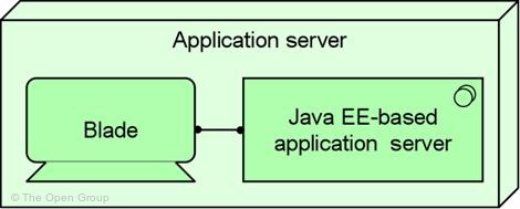
Example 24: Node
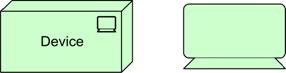
A device is defined as a hardware resource upon which artifacts may be stored or deployed for execution.
A device is a specialization of a node that represents a physical resource with processing capability. It is typically used to model hardware systems such as mainframes, PCs, or routers. Usually, they are part of a node together with system software. Devices may be composite; i.e., consist of sub-devices.
Devices can be interconnected by networks. Artifacts can be assigned to (i.e., deployed on) devices. System software can be assigned to a device. A node can contain one or more devices.
The name of a device should preferably be a noun referring to the type of hardware; e.g., “IBM System z mainframe”.
A device can consist of sub-devices.
Different icons may be used to distinguish between different types of devices; e.g. mainframes and PCs.
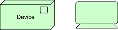
Figure 36: Device Notation
Example
The model below shows an example of a number of servers, modeled as devices, interconnected through a local area network (LAN).
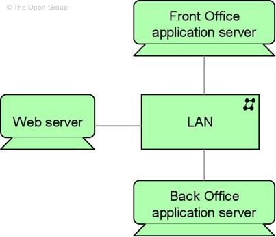
Example 25: Device
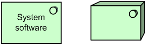
System software represents a software environment for specific types of components and objects that are deployed on it in the form of artifacts.
System software is a specialization of a node that is used to model the software environment in which artifacts run. This can be, for example, an operating system, a JEE application server, a database system, or a workflow engine. Also, system software can be used to represent, for example, communication middleware. Usually, system software is combined with a device representing the hardware environment to form a general node.
System software can be assigned to a device. Artifacts can be assigned to (i.e., deployed on) system software. A node can contain system software.
The name of system software should preferably be a noun referring to the type of execution environment; e.g., “JEE server”. System software may contain other system software; e.g., an operating system containing a database.

Figure 37: System Software Notation
Example
In the model below, we see a mainframe device that deploys two system software environments: a customer transaction server and a database management system (DBMS).
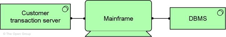
Example 26: System Software
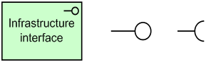
An infrastructure interface is defined as a point of access where infrastructure services offered by a node can be accessed by other nodes and application components.
An infrastructure interface specifies how the infrastructure services of a node can be accessed by other nodes (provided interface), or which functionality the node requires from its environment (required interface). An infrastructure interface exposes an infrastructure service to the environment. The same service may be exposed through different interfaces.
In a sense, an infrastructure interface specifies a kind of contract that a component realizing this interface must fulfill. This may include, for example, parameters, protocols used, pre- and post-conditions, and data formats.
An infrastructure interface may be part of a node through composition (not shown in the standard notation), which means that these interfaces are provided or required by that node, and can be used by other nodes. An infrastructure service can be assigned to an infrastructure interface, which exposes the service to the environment.
The name of an infrastructure interface should preferably be a noun.
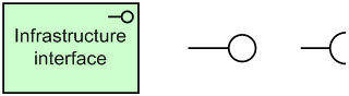
Figure 38: Infrastructure Interface Notations
Example
In the model below, we see a client infrastructure interface exposed, which is part of the client-server system software.
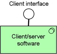
Example 27: Infrastructure Interface
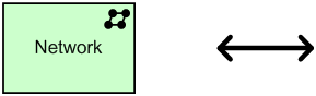
A network is defined as a communication medium between two or more devices.
A network represents the physical communication infrastructure. This may comprise one or more fixed or wireless network links. The most basic network is a single link between two devices. A network has properties such as bandwidth and latency. It embodies the physical realization of the logical communication paths between nodes.
A network connects two or more devices. A network realizes one or more communication paths.
A network can consist of sub-networks.
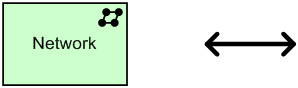
Figure 39: Network Notation, as Connection and as Box
Example
In the model below, a 100 Mb/s LAN network connects a mainframe and PC device.

Example 28: Network
A communication path is defined as a link between two or more nodes, through which these nodes can exchange data.
A communication path is used to model the logical communication relations between nodes. It is realized by one or more networks, which represent the physical communication links. The communication properties (e.g., bandwidth, latency) of a communication path are usually aggregated from these underlying networks.
A communication path connects two or more nodes. A communication path is realized by one or more networks. A communication path is atomic.
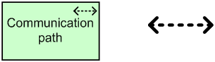
Figure 40: Communication Path Notation, as Connection and as Box
Example
In the model below, we see a communication path “message queuing” between an Application Server and a Client.
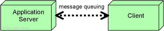
Example 29: Communication Path
Behavior elements in the technology layer are similar to the behavior elements in the other two layers. Also here, we make a distinction between the external behavior of nodes in terms of infrastructure services, and the internal behavior of these nodes; i.e., infrastructure functions that realize these services.
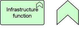
An infrastructure function is defined as a behavior element that groups infrastructural behavior that can be performed by a node.
An infrastructure function describes the internal behavior of a node; for the user of a node that performs an infrastructure function, this function is invisible. If its behavior is exposed externally, this is done through one or more infrastructure services. An infrastructure function abstracts from the way it is implemented. Only the necessary behavior is specified.
An infrastructure function may realize infrastructure services. Infrastructure services of other infrastructure functions may be used by an infrastructure function. An infrastructure function may access artifacts. A node may be assigned to an infrastructure function (which means that the node performs the infrastructure function). The name of an infrastructure function should preferably be a verb ending with “-ing”.

Figure 41: Infrastructure Function Notation
Example
In the model below, the database management system (DBMS) node performs two infrastructure functions: providing data access (realizing a data access service for application software), and managing data (realizing a data management service for database administration).
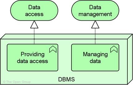
Example 30: Infrastructure Function
An infrastructure service is defined as an externally visible unit of functionality, provided by one or more nodes, exposed through well-defined interfaces, and meaningful to the environment.
An infrastructure service exposes the functionality of a node to its environment. This functionality is accessed through one or more infrastructure interfaces. It may require, use, and produce artifacts.
An infrastructure service should be meaningful from the point of view of the environment; it should provide a unit of functionality that is, in itself, useful to its users, such as application components and nodes.
Typical infrastructure services may, for example, include messaging, storage, naming, and directory services. It may access artifacts; e.g., a file containing a message.
An infrastructure service may be used by application components or nodes. An infrastructure service is realized by a node. An infrastructure service is exposed by a node by assigning it to its infrastructure interfaces. An infrastructure service may access artifacts.
The name of an infrastructure service should preferably be a verb ending with “‑ing”; e.g., “messaging”. Also, a name explicitly containing the word “service” may be used.
An infrastructure service may consist of sub-services.
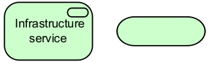
Figure 42: Infrastructure Service Notation
Example
In the model below, we see a Messaging service realized by Message-Oriented Middleware (MOM) system software.
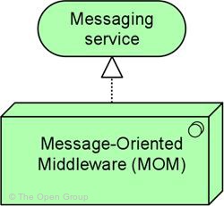
Example 31: Infrastructure Service
An artifact is a physical piece of information that is used or produced in a software development process, or by deployment and operation of a system. It is the representation, in the form of, for example, a file, of a data object, or an application component, and can be deployed on a node. The artifact concept has been taken from UML 2.0.
An artifact is defined as a physical piece of data that is used or produced in a software development process, or by deployment and operation of a system.
An artifact represents a concrete element in the physical world. It is typically used to model (software) products such as source files, executables, scripts, database tables, messages, documents, specifications, and model files. An instance (copy) of an artifact can be deployed on a node. An artifact could be used to represent a physical data component that realizes a data object.
An application component or system software may be realized by one or more artifacts. A data object may be realized by one or more artifacts. A node may be assigned to an artifact (i.e., the artifact is deployed on the node). Thus, the two typical ways to use the artifact concept are as an execution component or as a data file. In fact, these could be defined as specializations of the artifact concept.
The name of an artifact should preferably be the name of the file it represents; e.g., “order.jar”. An artifact may consist of sub-artifacts.
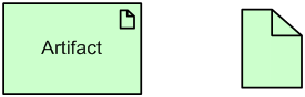
Figure 43: Artifact Notation
Example
In the example below, we see an artifact Risk management EJB, which represents a deployable unit of code, assigned to (deployed on) an application server.
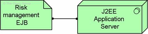
Example 32: Artifact
Table 3 gives an overview of the concepts at the technology layer, with their definitions.
Table 3: Technology Layer Concepts
|
Concept |
Definition |
Notation |
|
Node |
A computational resource upon which artifacts may be stored or deployed for execution. |
|
|
Device |
A hardware resource upon which artifacts may be stored or deployed for execution. |
|
|
Network |
A communication medium between two or more devices. |
|
|
Communication path |
A link between two or more nodes, through which these nodes can exchange data. |
|
|
Infrastructure interface |
A point of access where infrastructure services offered by a node can be accessed by other nodes and application components. |
|
|
System software |
A software environment for specific types of components and objects that are deployed on it in the form of artifacts. |
|
|
Infrastructure function |
A behavior element that groups infrastructural behavior that can be performed by a node. |
|
|
Infrastructure service |
An externally visible unit of functionality, provided by one or more nodes, exposed through well-defined interfaces, and meaningful to the environment. |
|
|
Artifact |
A physical piece of data that is used or produced in a software development process, or by deployment and operation of a system. |
|
Downloads of the ArchiMate documentation, are available under license from the ArchiMate information web site. The license is free to any organization wishing to use ArchiMate entirely for internal purposes (for example, to develop an information system architecture for use within that organization). A book is also available (in hardcopy and pdf) from The Open Group Bookstore as document C13L.