
Copyright © 2015 The Open Group


| < Previous | ▲ Home | Next > |
|
IT4IT Reference Architecture, Version 2.0 Technical Standard Copyright © 2015 The Open Group |
|
The IT4IT Reference Architecture provides a “standard, repeatable model” for creating an IT management ecosystem, set in the context of a value chain-based IT operating model. It is intended to help organizations adapt to changes in technology, process, and methods without having to re-factor the management architecture to accommodate every shift. It is also intended to function as design guidance for suppliers of IT management products and services.
This chapter does not provide the details of the IT4IT Reference Architecture, but uses portions of it for illustrative and example purposes. For a comprehensive overview of the IT4IT Reference Architecture and associated content, please see the appropriate documents contained in the IT4IT website at www.opengroup.org/it4it.
The IT4IT Reference Architecture is communicated using multiple levels of abstraction which is similar to the approach employed by other frameworks such as eTOM from the TM Forum. Each abstraction level expands on the prior to expose more details and prescriptive guidance. The upper levels (1-3) are vendor-agnostic and provide more generic views that are suitable for strategy and planning purposes as well as for creating IT management product roadmaps. The lower levels (4-5) provide more specific details, ultimately arriving at implementation level or vendor-owned/controlled information. Content at these levels is suitable for developing implementation plans and for facilitating product design. The IT4IT Reference Architecture defines five abstraction levels as depicted below:
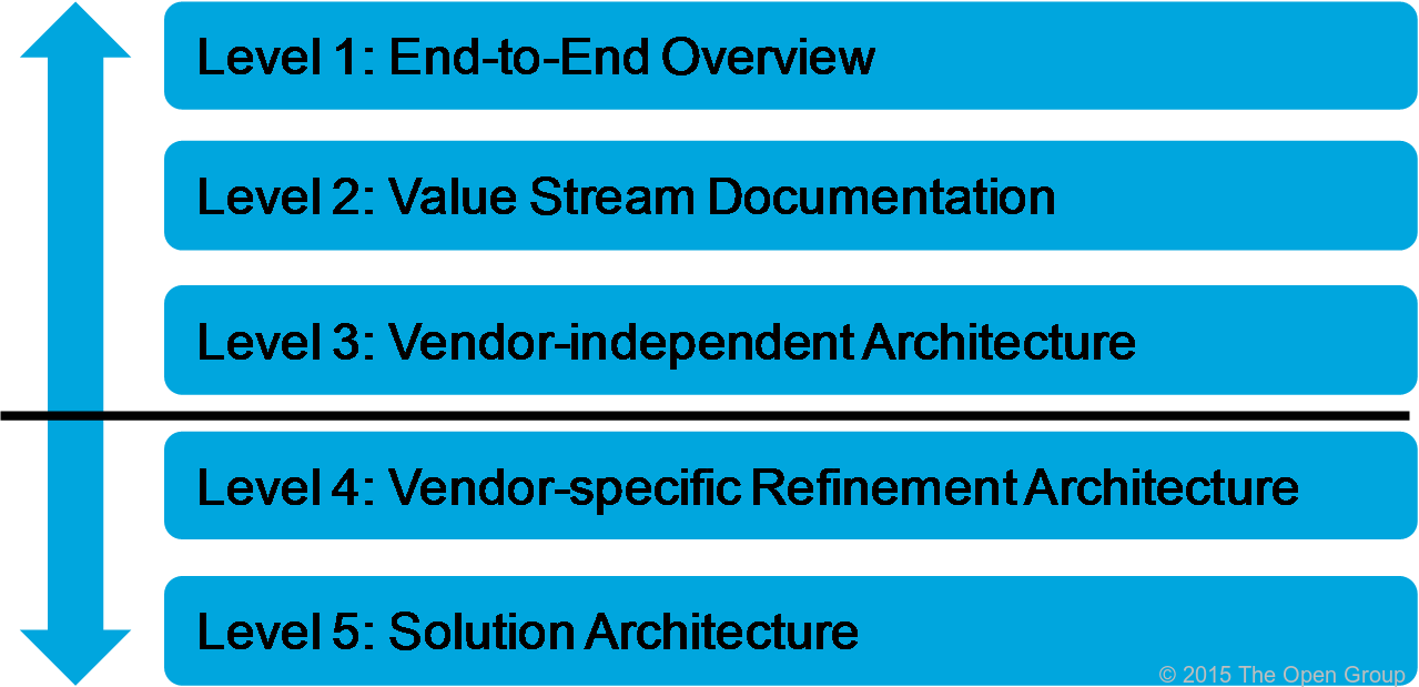
Figure 14: IT4IT Reference Architecture Levels
The balance of this chapter provides an overview for how to interpret the concepts and architectural constructs introduced at each level of abstraction for the IT4IT Reference Architecture. Levels 1 and 2 utilize a simplified class model and an informal notation to introduce and explain concepts. An informal notation was selected at these levels so that the architecture would be easily understood by non-architects. Where appropriate, the associated formal notation, expressed in the ArchiMate modeling language or UML terms, is also depicted. Level 3 and beyond are more applicable to architects and thus the formal notation is the preferred means of communicating concepts at this level. The IT4IT Reference Architecture focuses on documenting and governing Levels 1 to 3. Levels 4 and 5 are controlled by product and service providers or potentially other forums, and the IT4IT Reference Architecture merely provides exemplar guidance at these levels.
Most of the terminology used in the architecture is based on or derived from existing industry standard taxonomies. The architecture does introduce some new terms but this is only done when no other existing term could be utilized to express the intended meaning of the concept.
Abstraction Level 1 is considered the “overview level”. It provides a holistic model of the IT4IT Reference Architecture, introducing the core terms and concepts that underpin the architecture. It depicts, at a high level, the foundation controls an IT organization needs in place to standardize and automate and manage the IT Value Chain.
At this level five core concepts are introduced that are central to the IT4IT Reference Architecture body of work:
• Value Streams
• Functional Components
• Service Lifecycle Data Objects (key data objects)
• Service Model Backbone Data Objects (service backbone data objects)
• Relationships
The relationships among these five concepts are shown in Figure 15. (Note that the graphic uses UML notation to depict the multiplicity).
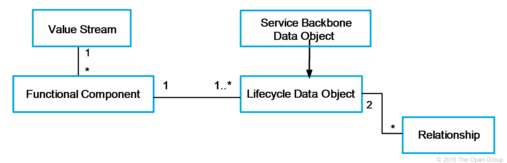
Figure 15: Level 1 Class Model
An important point to understand from the class model in Figure 15 is that all data objects are considered service lifecycle data objects. This means that the “service backbone data objects” that are used to represent the Service Model are a type of lifecycle data object. The IT4IT documentation treats service backbone data objects differently because they play a special role in the Reference Architecture.
Also notice that capability is missing from the diagram. While capability mapping remains an important activity for IT organizations, it is not included as part of the normative documentation. Instead, other documents (guidance documents) will provide this level of detail. The objective of the IT4IT Reference Architecture is to convey, in a prescriptive fashion, the key data objects, relationships, and components that are foundational for all IT organizations.
The following sections expand on each of the core concepts introduced in Level 1.
The IT4IT Reference Architecture uses the value stream construct as a way of grouping the functional components and data objects together to provide context for where value is being created/delivered. There are four value streams within the model:
• Strategy to Portfolio (S2P)
• Requirement to Deploy (R2D)
• Request to Fulfill (R2F)
• Detect to Correct (D2C)
There are also supporting functions within the value chain model such as Supplier Management, Asset Management, Human Resource Management, Legal, and IT Financial Management.
Note: While there are various opinions on the concept of process, this standard does not define the value streams to be a macro-process. As stated previously, the IT4IT Reference Architecture does not dictate a process or capability model. Further, the architecture has been tested to work equally well in lean, agile, and traditional waterfall process scenarios.
Notation and Naming
In the formal notation, value streams can be modeled in the ArchiMate language as “Business Functions”. However, in the informal notation at Levels 1 and 2 they are only used to depict a grouping of the functional components (Figure 22).
A functional component is the smallest unit of technology that can stand on its own and be useful as a whole to an IT practitioner (or IT service provider). It must have defined input(s) and output(s) that are data objects and must have an impact on a key data object; for example, create, update, delete. Typically, a functional component controls and/or manages a single type of data object but this is not dictated by the architecture.
In the IT4IT Reference Architecture, functional components are aligned with specific value streams and supporting functions. Components aligned with a given value stream are considered its “primary” functional components. Functional components that affect key data objects for a given value stream but aren’t primary to that value stream are considered “secondary” functional components. The Reference Architecture uses different colors to distinguish between primary and secondary functional components (see Section 3.4.3 for additional details).
Examples of functional components include Event, Project, Defect, etc. The IT4IT Reference Architecture contains only those functional components that have an impact on key data objects. There will be other technology components and management systems that are used by IT organizations in the normal course of business but those are not considered to be part of the prescriptive IT4IT Reference Architecture. Examples of these types of components could include corporate finance systems, human resource applications, and contracts management systems.
Notation and Naming
The IT4IT Reference Architecture uses both formal and informal notation style and a visual syntax to depict functional components. At Level 1 the informal notation renders primary functional components as blue rectangles (see Figure 16). Secondary functional components are rendered as gray rectangles. Functional components are represented formally in the ArchiMate language using the “Application Component” type.
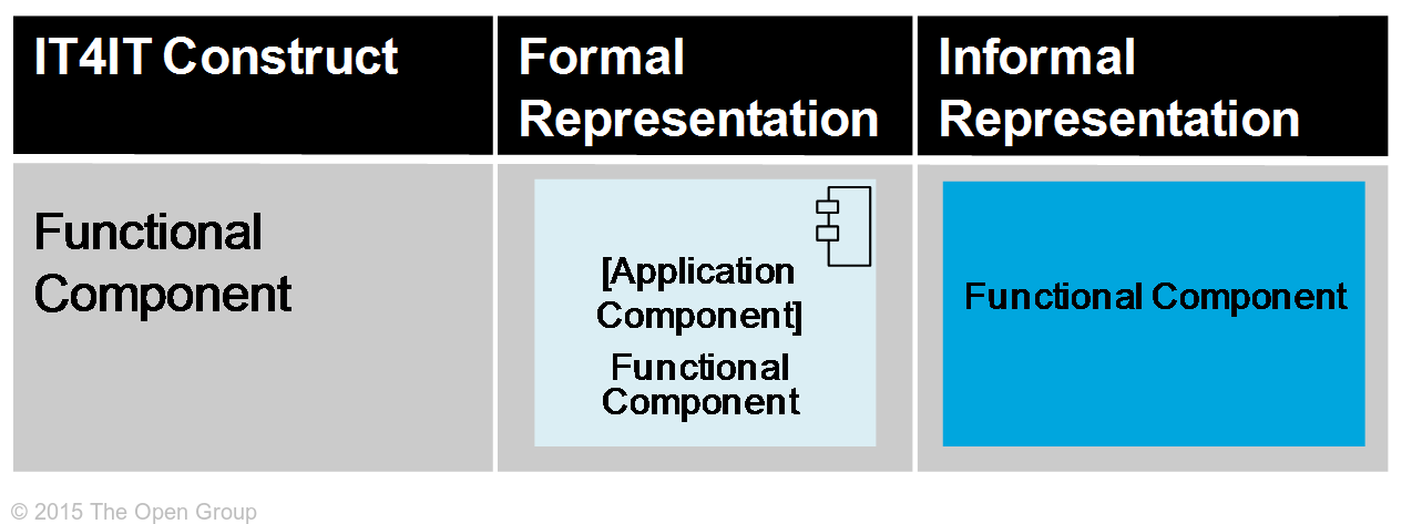
Figure 16: Functional Component Notation
While a functional component may control one or more data object types, a single data object can only be controlled by one functional component. To communicate this visually, an informal notation that embeds the “controlled” data object in the functional component is used, as depicted in Figure 17.
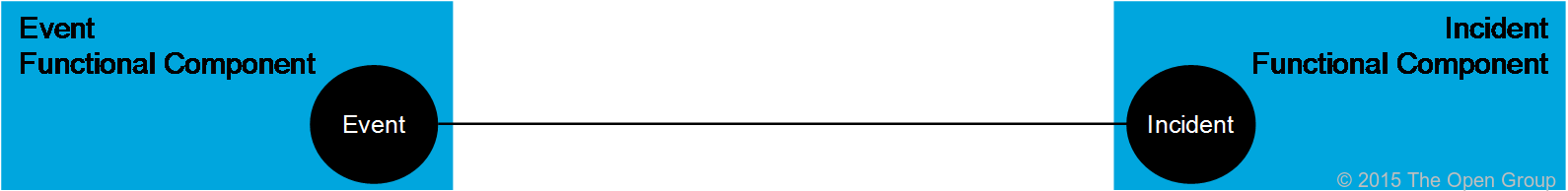
Figure 17: Functional Component to Data Object Notation
Diagrams can be complex and require clear “visual syntax” to help the reader interpret the elements and their relationships. Text is used to describe the emphasis of the functional component. Figure 18 depicts the informal notation of the functional components and their associated data objects.
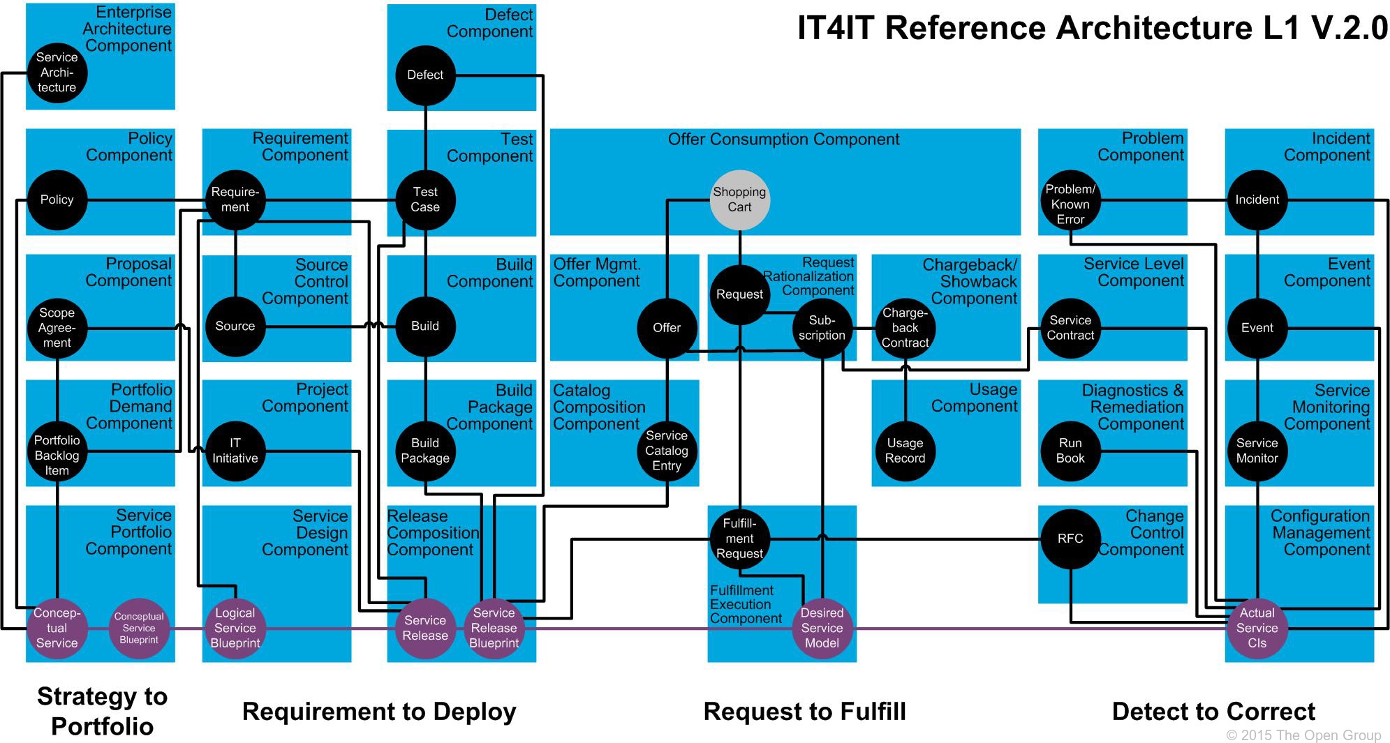
Figure 18: Functional Components and Data Objects
A service lifecycle data object (lifecycle data object) represents data (records, information, and so on) that annotate or model an aspect of a service being offered by IT. Data objects can take a digital or physical form and can be comprised of structured, semi-structured, or unstructured data. Our definition of service lifecycle data object is aligned contextually with the OMG definition of artifact. In UML, the OMG defines artifact as:
“the specification of a physical piece of information that is used or produced by a software development process, or by deployment and operation of a system. Examples of artifacts include model files, source files, scripts, and binary executable files, a table in a database system, a development deliverable, or a word-processing document, a mail message.”
Examples of data objects include incident records, training videos, requirements documents, project plans, etc. These types of data objects contribute in some way to the service over the course of its lifecycle. There are also “special” data objects that represent an abstraction or view of a specific service being offered. For example, a system diagram, Service Catalog Entry, or a binary executable file provide a “view” of a service to various personas at different stages of the service lifecycle. These special data objects and their relationships form a “backbone” that binds together all of the information needed to offer and manage a service, thus they are referred to as Service Model Backbone data objects (backbone data objects).
The central focus of the IT4IT work has been to identify the data objects that play a “key” role in the service lifecycle. In other words, the Reference Architecture focuses exclusively on the data objects that are mandatory for ensuring end-to-end traceability of the service operationally and/or financially. There are other data objects used across the IT function to facilitate various needs or activities (e.g., company-specific processes), but these are considered to be secondary or auxiliary and outside the prescriptive control of the IT4IT Reference Architecture.
Notation and Naming
As with functional components, the IT4IT Reference Architecture utilizes both formal and informal notations for data objects so that the work can be easily understood by both architects and non-architects. In the Level 1 model an informal notation that depicts data objects as circles is used. Color is used to specify whether a data object is key (black) or a backbone data object (purple). Data objects are modeled formally in the ArchiMate language using the “Data Object” type.
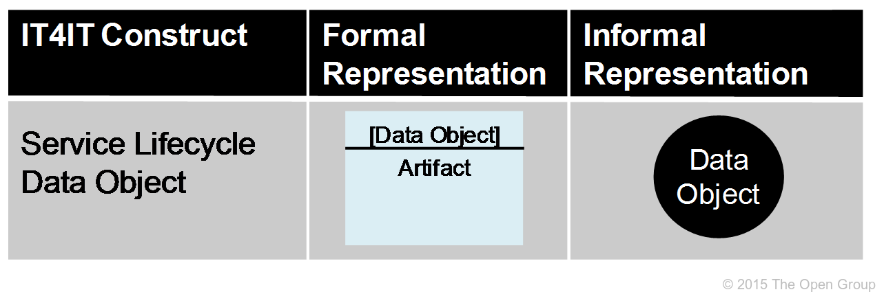
Figure 19: Service Lifecycle Data Object Notation
Text is also important in communicating the concepts represented in the model. According to dual-coding theory, using text and graphics together to convey information is more effective than using either on their own. Further, the IT4IT Reference Architecture attempts to avoid using text that creates collisions between architectural layers (e.g., business function, data, and implementation layers). Level 1 introduces naming conventions for data objects that are rooted in the well-known IT frameworks and standards.
The service lifecycle data objects represent the authoritative source data and/or master data for managing the business of IT. In IT taxonomy, “system of record” is a term that is commonly used as a synonym for an authoritative source system.
An important aspect of the IT4IT Reference Architecture is defining not only the data objects, but the essential relationships between them. The data objects, combined with their relationships and inter-dependencies, form the “system of record fabric” for IT management (see Figure 20). These relationships are referred to as system of record integrations (record-centric, SoR in short form). Compliance with the prescribed system of record relationship mapping will ensure end-to-end traceability operationally and financially, and ensure Service Model integrity can be maintained across the lifecycle. This also eliminates the confusion and collisions that result from process re-engineering efforts that frequently occur within the various IT functions.
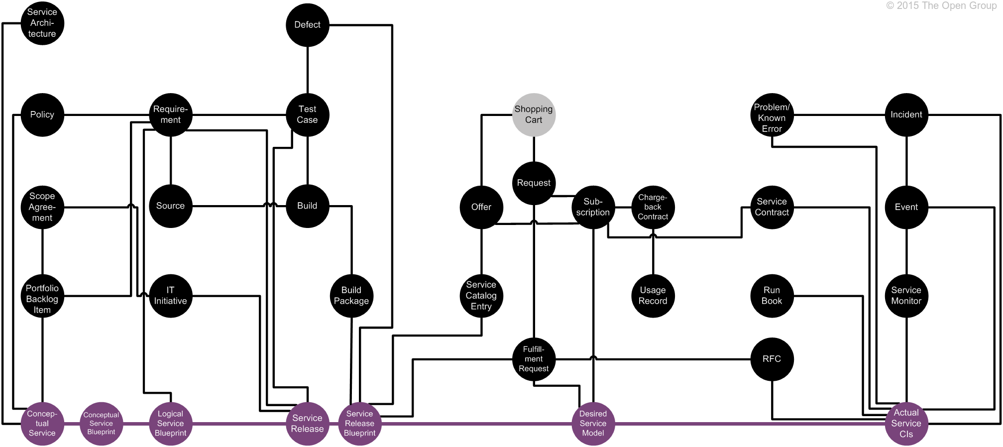
Figure 20: System of Record Fabric
Notation and Naming
Abstraction Level 1 expresses the essential relationships as lines between the participating data objects. Here, the formal and informal notation is identical; a line connecting one data object with another.
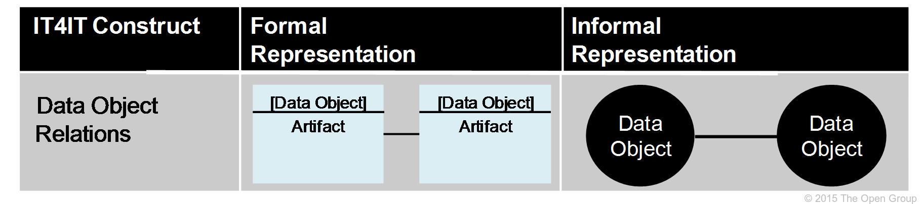
Figure 21: Relationships Notation
Figure 21 depicts the Level 1 model for the IT4IT Reference Architecture rendered using the informal notation. In discussions on the IT4IT Reference Architecture this graphic should be used to represent the content contained in abstraction Level 1.

Figure 22: IT4IT Level 1 Reference Architecture Model
Abstraction at Level 2 expands on the concepts introduced in Level 1, providing definitions and details and introducing a few more concepts, including:
• Relationships between data objects are updated with multiplicity/cardinality attributes (e.g., one-to-one, one to many, many-to-many).
• The concept of data flow between functional components is introduced.
• The data flows are refined to depict integrations to build out the system of record fabric.
• The relationships between capability disciplines and functional components are introduced but they are not part of the normative reference and are presented as guidance.
The Level 1 class diagram in Figure 15 is expanded to reflect these additions in Figure 23 below. Note that the terms system of record and system of engagement integration are explained later in this section.
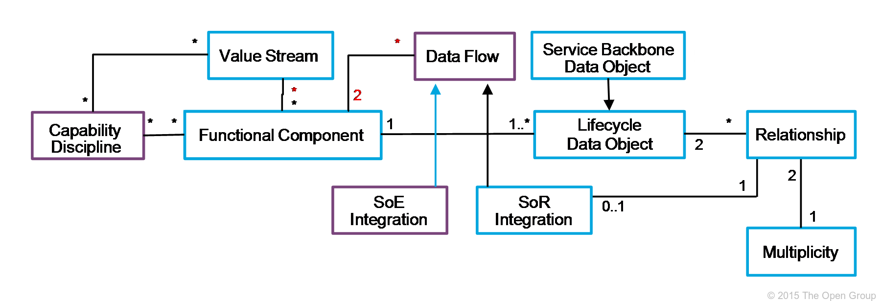
Figure 23: Level 2 Class Model
The Level 2 concepts are communicated through a set of normative documents and simplified views into the definitive vendor-independent model maintained at Level 3.
Multiplicity (sometimes referred to as “cardinality”) describes the number of allowable instances of an element. Multiplicity intervals have a lower bound and a (possibly infinite) upper bound. In the IT4IT Reference Architecture the term is used to describe the relationship between data object instances.
For example, there is a one-to-n (1:n) relationship between “request” and “request fulfillment” data objects. This indicates that a single request can result in multiple fulfillments. In the instance of a “laptop”, a service request might require a request for the laptop and another for a mouse and one for a user account. Therefore, the one request generated multiple request fulfillment data objects.
The IT4IT Reference Architecture only defines the key relationships – those that contribute to the advancement of the service lifecycle. There are other relationships that may be needed to satisfy the specific policies, processes, or capabilities but they are not considered to be part of the prescriptive guidance.
Notation and Naming
For clarity, we are explicitly showing one-to-many relationships using UML notation. An information notation is also used to describe multiplicity at Levels 1 and 2. Again, the informal notation is used so that it can be understandable to non-architects.
|
IT4IT Multiplicity |
Formal Representation |
Informal Representation |
|
One to no more than one |
0..1:0..1 |
1:1 |
|
One-to-many |
0..1:* |
1:n |
|
Many-to-many |
*..*:* |
n:m |
A data flow describes the flow of information between functional components. The technique used to facilitate the flow is not specified. The reason for adding the data flow information to the Level 2 diagrams is to expose the need for integration and data sharing. It also helps to demonstrate the dependencies between functional components and how they can work together to deliver value.
The data flows are not considered part of the normative specification of the IT4IT Reference Architecture and are offered at Level 2 as guidance to help interpret the various value stream diagrams.
Notation and Naming
An informal notation is used for data flows, drawn as a dotted line with a solid end-arrow indicating the direction of the flow. The data/information being transferred should be depicted on the line.
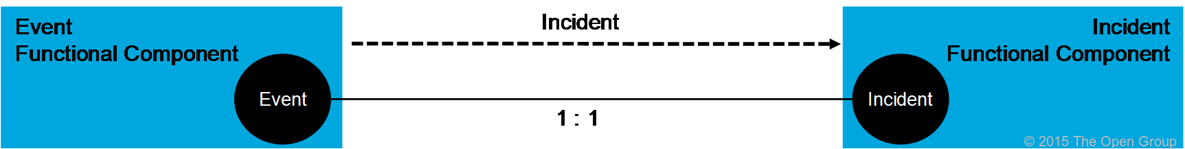
Figure 24: Data Flow Notation
In the Level 1 “Relationships” section (Section 4.2.2.4) the concept of authoritative source system or system of record was introduced. In order for the system of record relationships to be sustained over the course of the service lifecycle, integrations between functional components controlling the key data objects must be well defined. This requires that some data flows be “refined” into system of record integration specifications. These specifications become part of the normative IT4IT Reference Architecture.
For a data flow to be refined into a system of record integration, the following conditions must be satisfied:
• The data flow creates a relationship/dependency between two data objects in the functional components involved in the data flow.
• The two data objects must have a direct relationship to be maintained.
• The lifecycles of the two data objects are interlocked. This means that updates to one data object can have consequences on the other data object.
The reason for defining these integrations as part of the architecture is to ensure the integrity of the system of record fabric and the Service Model. IT organizations are likely to implement products from multiple suppliers for their IT4IT Reference Architecture and without this specification there is no way to ensure consistency in data flows.
A system of record integration is depicted in Figure 25. This figure provides an illustrative example that describes the state dependency between the “Event” and “Incident” data objects. Here, Events generate Incidents that results in a relationship and dependency between these two data objects.
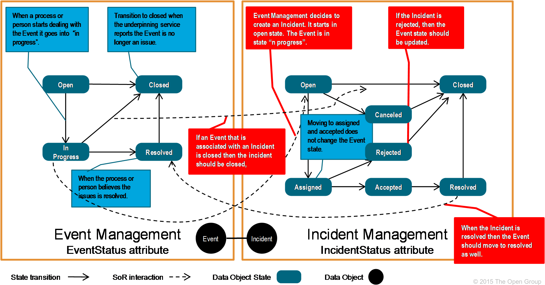
Figure 25: Data Object State Model Dependency Illustration
Relationships are also formed between functional components to enable humans and machines to interact with and/or take action on the data objects. These relationships are called system of engagement integrations (experience-centric integration, SoE in short form). These integrations are derived from value stream use-cases and user stories and are offered as guidance rather than prescriptive practices. The intent is to demonstrate to the reader how data object relationships stimulate and/or are affected by human-to-machine and machine-to-machine interactions. Figure 26 provides an illustration of system of engagement integrations. It is merely an illustration and not an exact depiction of specific integrations in the IT4IT Reference Architecture.
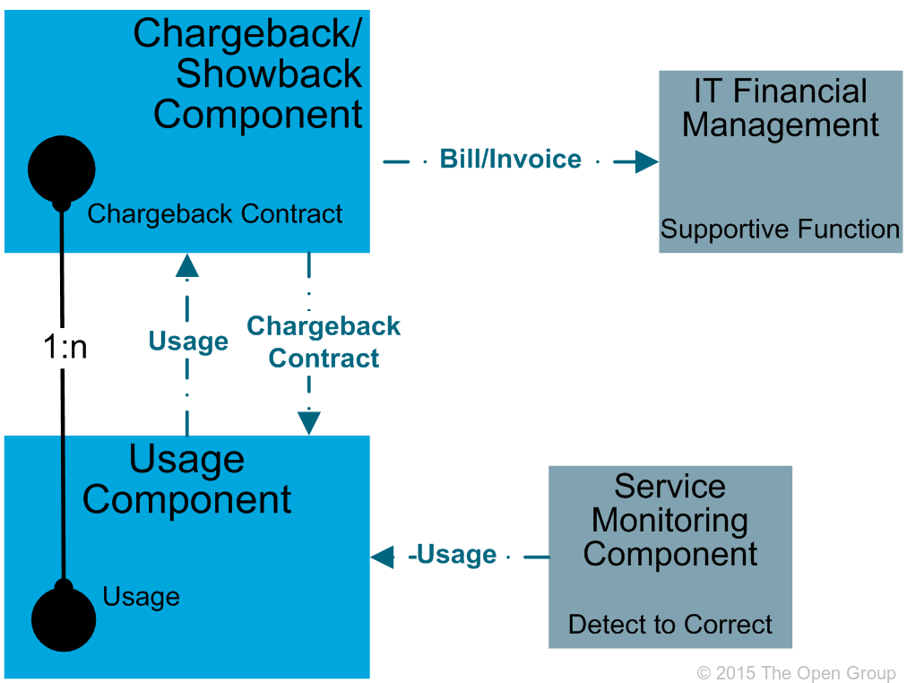
Figure 26: System of Engagement Integration Illustration
Naming and Notation
At Level 2 the informal notation depicts system of record integrations using a black dotted line with solid end-arrow accompanied by the name of the data object that is transferred to create the relationship. No subsequent information is shown as being passed on an ongoing basis to maintain or update either data object. The formal notation in the ArchiMate language uses the collaboration and interaction concepts. System of engagement integrations are only depicted using the informal notation and are rendered as a blue dotted line with a solid end-arrow accompanied by the name of the data object being acted upon.
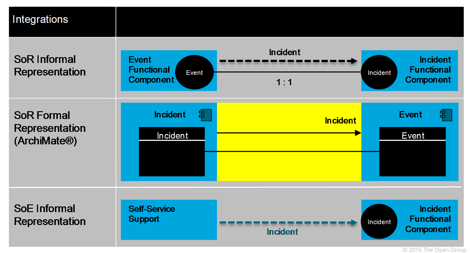
Figure 27: System of Record and Engagement Integration Notation
A capability is the ability of an organization to produce an outcome of value through the utilization of people, process, and technology. A list of capabilities at the discipline level of granularity (capability disciplines) is being compiled. These come from ITIL, COBIT, SAFe, PMBOK, and other industry sources. It is not the focus or intent of the IT4IT Reference Architecture to redefine or modify the existing work that has been done around IT capabilities; instead a comprehensive list is being compiled and it defines the relationships between functional components and capability disciplines.
Capability discipline documentation is considered “guidance” and not part of the normative IT4IT Reference Architecture.
Notation and Naming
While capability disciplines are not part of the normative reference, both an informal and formal notation are used to describe them for consistency across the architecture. The informal notation uses green boxes to depict primary capability disciplines (or discipline capability) and solid lines with solid end-arrows to show relationships and inter-dependencies. Secondary (or auxiliary) capability disciplines are depicted using gray boxes. Interfaces to “other” capabilities are depicted using white boxes.
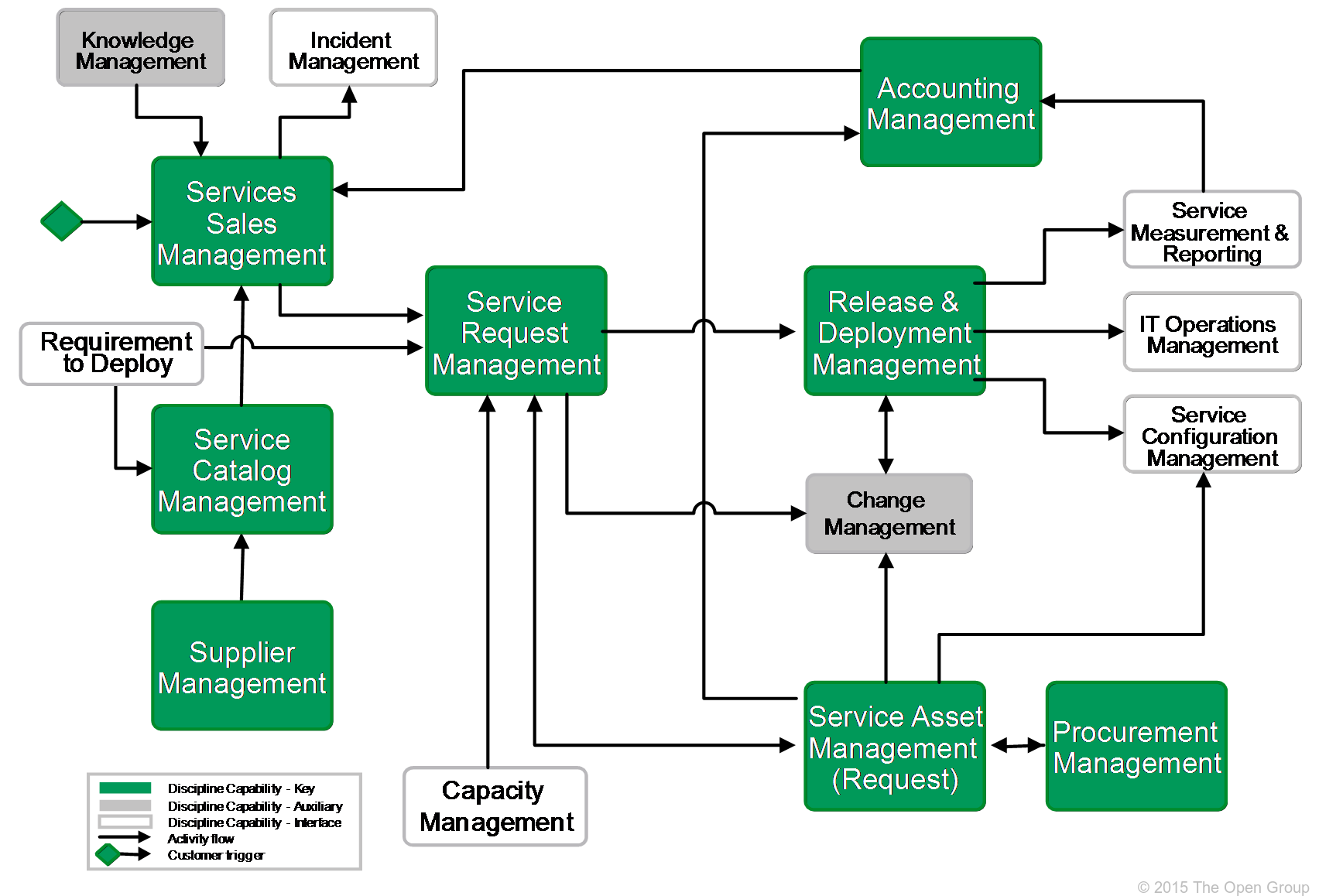
Figure 28: Capability Discipline Informal Notation
At the time of approval of this standard, the ArchiMate language does not currently recognize the concept of “capability” or “discipline”, so for now in the formal notation, the “business function” construct has been utilized.
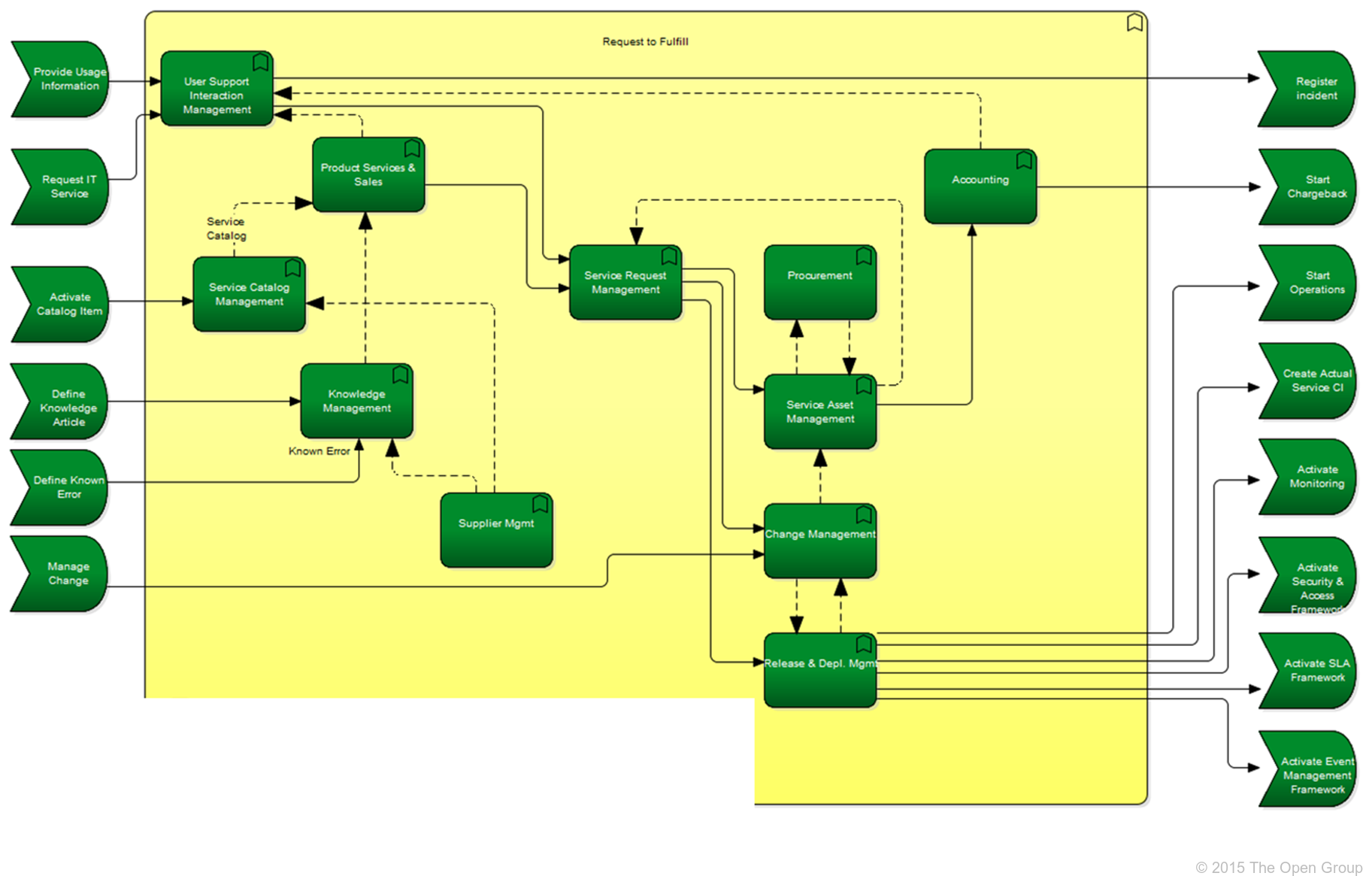
Figure 29: Capability Discipline Formal Notation
Figure 30 provides an example of a Level 2 model/diagram using the informal notation. This example is the Request to Fulfill (R2F) Value Stream and in discussions on the IT4IT Reference Architecture this graphic represents the content contained in abstraction Level 2.
Figure 30: Example Level 2 Diagram (R2F Value Stream)
Levels 1 to 2 use the informal notation as the primary means of communicating concepts to a general audience of non-architects; the formal notation being provided for the architect community. At abstraction Level 3 this changes and the formal notation (ArchiMate language and UML) is the primary method for communicating the IT4IT Reference Architecture specification. Level 3 adds more details for data object definitions, introducing essential attributes for key data objects. It also introduces the concepts of scenarios and essential services. Figure 31 shows the additions to the IT4IT Reference Architecture class model at Level 3.
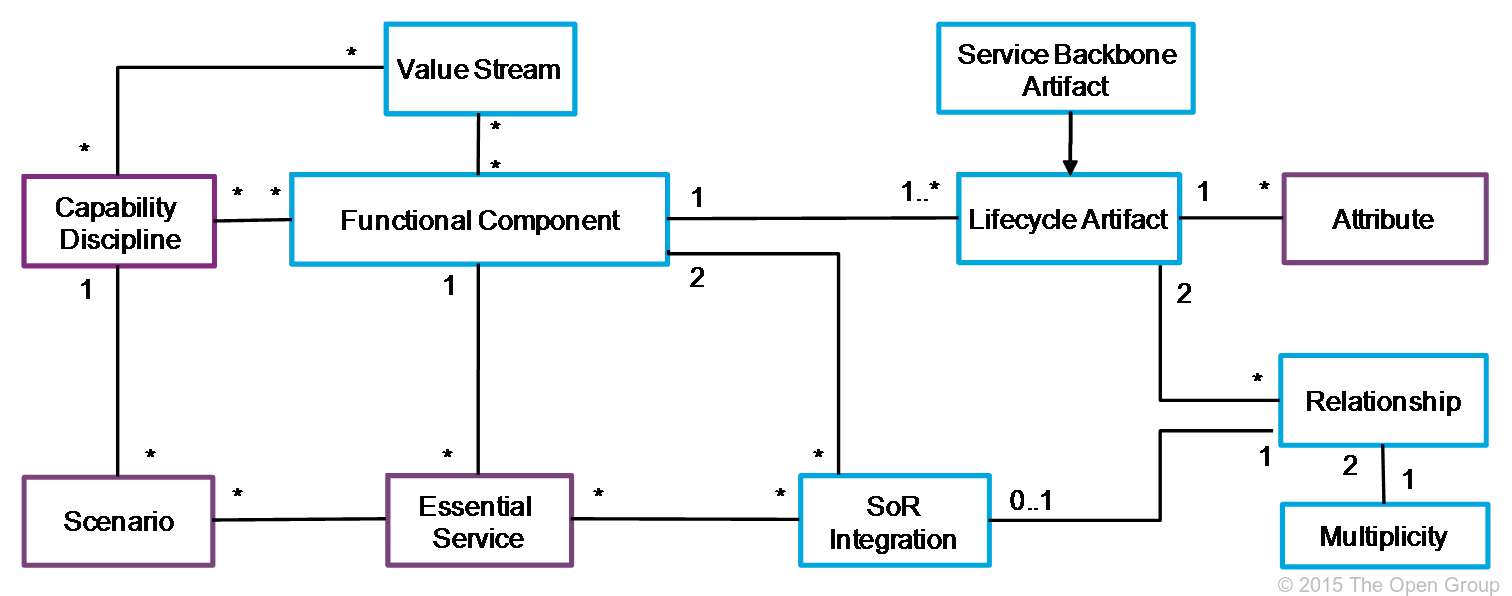
Figure 31: Level 3 Class Model
In the IT4IT Reference Architecture, a scenario is a narrative that describes foreseeable interactions of user roles (or “actors”) and a system (or functional component). The term is analogous with “epics” or “theme” in agile development methodologies. Scenarios are used to explain, enhance, or modify the Reference Architecture and are described using a structured template that includes a formal notation that can be expressed in the ArchiMate language. This enables readers to consume the information more easily as multiple organizations may produce and/or contribute to scenarios over time.
The following list is an example of the “scenario master document content”:
• Introduction: High-level description of the scenario to be described along with the goal to be achieved.
• Requirements: Requirements model the properties of the elements that are needed to achieve the “ends” that are modeled by the goals. In this respect, requirements represent the “means” to realize goals.
• Process Flow: An explanation on the process flow in the organization. This example explains how an Incident is handled using existing Knowledge.
Note: Process is not part of the normative reference in the IT4IT Reference Architecture.
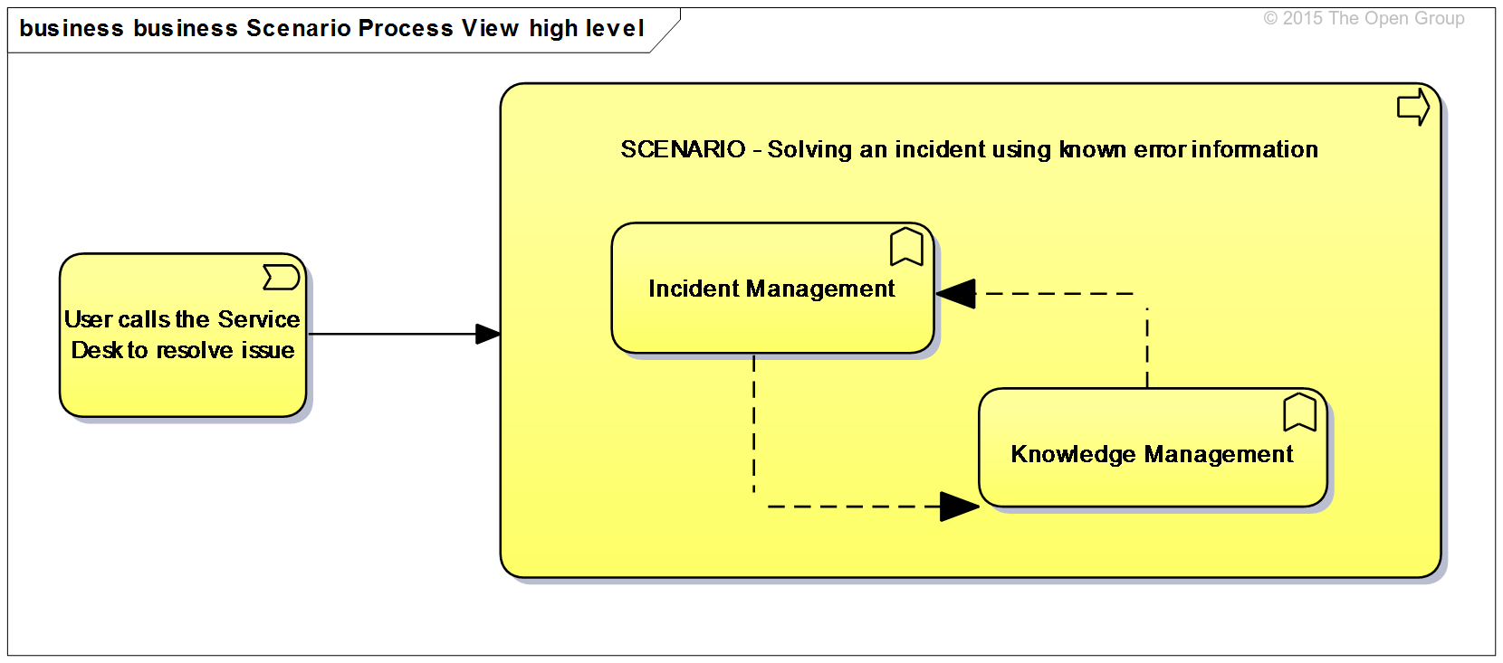
Figure 32: Scenario Process Flow Example
• Automation Specification using the Reference Architecture: Explains how the process is to be supported by the Reference Architecture. In the example two views would be created: one showing an Incident Management capability and another view for the Knowledge Management capability. The view should provide more information on how the functional components are aligned with the capabilities to automate the scenario.
• Essential Services Supporting the Scenario: See Section 4.2.6.3.
• Data Objects and Essential Attributes: Describes the data objects that are involved and the attributes of the data objects that are needed or impacted.
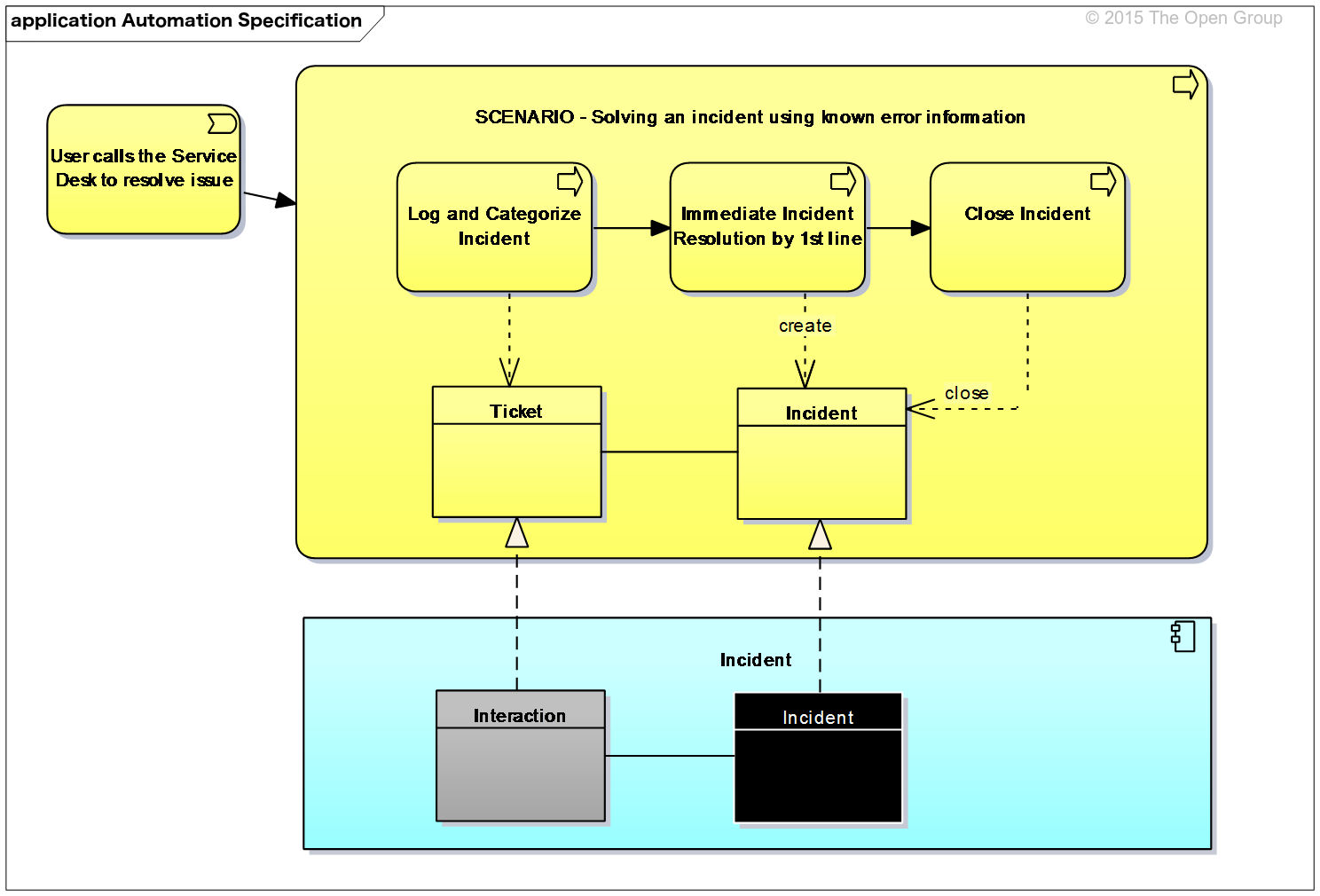
Figure 33: Essential Service Diagram Example
• Proposed changes to the Reference Architecture:
Scenarios currently under construction as of Version 2.0 of the IT4IT Reference Architecture include the following:
— IT Financial Management – IT service cost transparency
— Agile Scenario – DevOps, also including the Kanban/SAFe Positioning White Paper
— Multi-vendor Incident Management
See also Section 1.6.
As described in Levels 1 and 2, data objects represent the data exchanged between functional components. At abstraction Level 3 it is important to specify the attributes of the objects that must be present (those deemed essential) in the exchange. Here, the minimum set of attributes that are required to maintain the integrity of the system of record fabric are defined. These also contribute to the formation of the canonical data model that underpins the IT4IT Reference Architecture. Often, IT management products will provide more information/attributes, but at Level 3 only the vendor-independent minimum that all should include is defined.
The most basic essential attributes are a “unique identifier” and the “data object lifecycle status”. Often there will be attributes that identify the relationships to other data objects in the IT4IT model.
For example, Figure 34 depicts the Event to Incident relationship. Here, the essential attributes that uniquely identify an Event and an Incident are shown. In addition there would be a data object lifecycle attribute that describes whether an Event is open, closed, in progress, or resolved. The Incident data object would have attributes that connect it with the related Event(s) and with potential problem records. It would also connect with the related Configuration Item (CI) data objects.
As of Version 2.0 of the IT4IT Reference Architecture, the specification is still being developed so there is no list of “approved” essential attributes and Figure 34 is merely an example included for illustrative purposes.
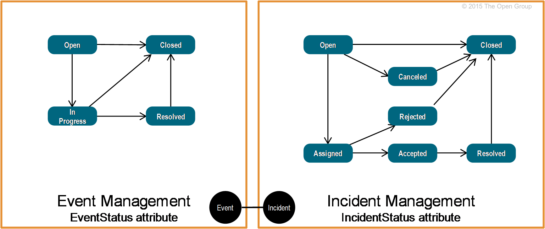
Figure 34: Essential Attributes Example
Notation and Naming
UML has been chosen as the notation for essential attributes (see Figure 35).
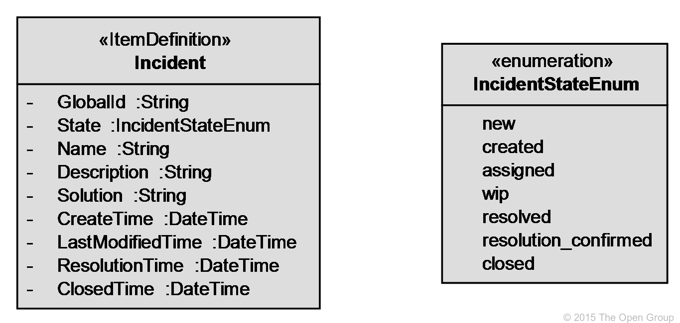
Figure 35: Essential Attributes Notation
In the IT4IT Reference Architecture, the essential service concept describes a means of facilitating integration between functional components or to take action on a data object (e.g., CRUD). Essential services are typically implemented as an API, web service, or micro-service with a well-defined set of parameters. The goal of essential services is to eliminate the need for point-to-point integrations between IT management products. They are defined by examining the data objects and specifying the attributes, parameters, etc. The result ultimately becomes part of the canonical data model.
As of Version 2.0, the specification is still being developed so there is no list of “approved” essential services. However, examples might include services such as: acknowledge event, register incident, manage incident, and so on.
Notation and Naming
Essential services can be modeled in the ArchiMate language using the “Application Service” construct. In the informal notation at Level 3 they are depicted as an oval inside a functional component element, as in Figure 36.
Level 3 demonstrates how system of record integrations are implemented using essential services to maintain the relationship between data objects. Figure 36 depicts the essential services exposed by different functional components in the D2C Value Stream. Here how such integrations maintain the state and relationship between the Event and Incident data objects is shown.
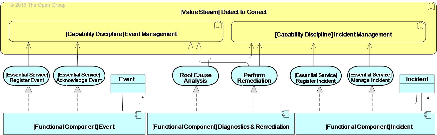
Figure 36: Example of Functional Components, Data Objects, and Essential Services
Figure 37 provides an example of the Level 3 ArchiMate notation guidelines. Where constructs are used for multiple purposes the name reflects how it is being used. For example, the Business Function construct is used to represent Value Chain, Value Stream, and Capability Discipline and when this happens the name will reflect which entity is represented.
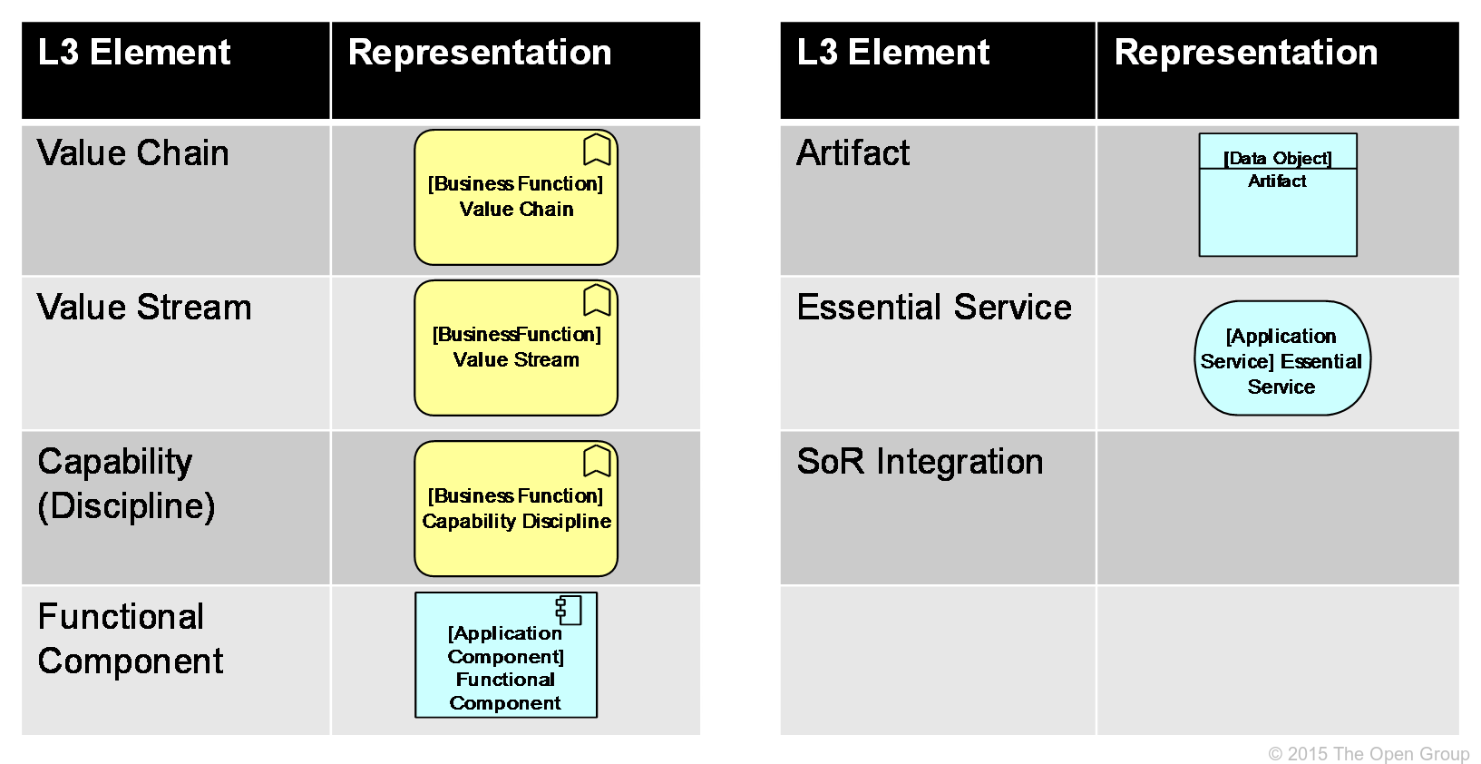
Figure 37: Level 3 Notation Guide
Levels 4 and 5 are owned and controlled by suppliers of IT management products and services. The IT4IT Reference Architecture has no direct control over defining and/or approving content at these abstraction layers. What is provided in this section are recommendations and examples of typical things would be expected at these levels.
For example, vendors might add essential services to the baseline or add functional components to differentiate their product or offering. The principle to be applied here is that whatever is added should build from and not change the prescriptive model defined in Levels 1 to 3.
Abstraction Level 4 is where the architecture becomes more product design and implementation-oriented. Here, for example, providers of IT management products and services can design/specify their service, interface, and exchange models which should be derived from Level 3 content. Other examples of Level 4 content might include:
• Defining extensions to the standard – “these essential attributes are being used, but these are added for the following reasons ...
• Adding data objects – “these non-key data objects were added, and are using the same notation style to reflect how they build off the baseline architecture”
• Additional notations – “the ArchiMate language is used for explaining scenarios and UML for the data models”
• Introduction of process – might introduce/model practitioner-level processes within scenarios
• Canonical data model – might introduce the vendor-specific canonical data model for their IT management products
• Integrations – might specify the techniques/methods used in implementing system of record integrations
Regardless of the how the vendor chooses to adapt and implement the architecture, it must be able to be mapped back into what is specified at Levels 1 to 3.
Abstraction Level 5 provides vendor-specific representations for an implementation of part or all of the Reference Architecture. It is the level at which the specifications and/or functionality for IT management products and services are provided. Deviations and adaptations to the Reference Architecture are also documented here. Examples of content at Level 5 might include:
• The structure used by vendor X to implement the D2C Value Stream.
• Vendor Y uses the “timestamp” essential attribute on the Event data object but names it “timeofday”.
• Vendor Z uses a product called ServiceXchange as the platform for essential services.
Notation and naming at Level 5 is vendor-owned/controlled but should reflect adherence to the baseline architecture and prescriptive guidance in Levels 1 to 3.
| < Previous | ▲ Home | Next > |