In addition to the generic elements outlined in Chapter 4, the ArchiMate language defines a core set of generic relationships, each of which can connect a predefined set of source and target concepts (in most cases elements, but in a few cases also other relationships). Many of these relationships are ‘overloaded’; i.e., their exact meaning differs depending on the source and destination concepts that they connect.
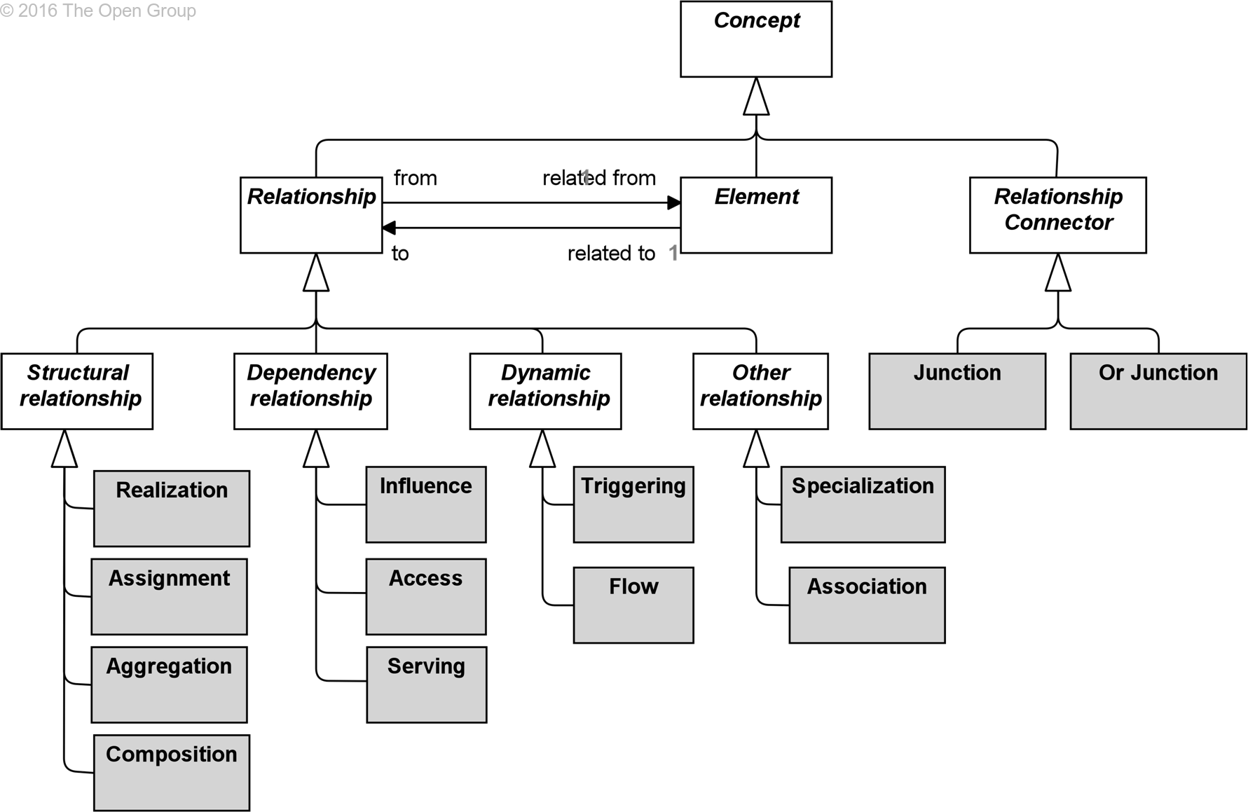
The relationships are classified as follows (see Figure 19):
• Structural relationships, which model the static construction or composition of concepts of the same or different types
• Dependency relationships, which model how elements are used to support other elements
• Dynamic relationships, which are used to model behavioral dependencies between elements
• Other relationships, which do not fall into one of the above categories
Figure 19: Overview of Relationships
Figure 19 shows that each relationship has exactly one ‘from’ and one ‘to’ concept (element or relationship) as endpoints. It does not show which types of concepts are permitted as endpoints. For the sake of readability, the metamodel figures throughout this document do not show all possible relationships in the language. Section 5.6 describes a set of derivation rules to derive indirect relationships between elements in a model. Aggregation, composition, and specialization relationships are always permitted between two elements of the same type, and association is always allowed between any two elements, and between any element and relationship. The exact specification of permitted relationships is given in Appendix B.
Structural relationships represent the ‘static’ coherence within an architecture. The composing concept (the ‘from’ side of the relationship) is always an element; the composed concept (the ‘to’ side of the relationship) may in some cases also be another relationship.
As an alternative to the graphical notations proposed in this section, structural relationships may also be expressed by means of nesting of the composed concept within the composing element. Note, however, that this can lead to ambiguous models, in case multiple structural relationships are allowed between these elements.
The composition relationship indicates that an element consists of one or more other elements.
The composition relationship has been inspired by the composition relationship in UML class diagrams. In contrast to the aggregation relationship, the composed concept can be part of only one composition.
A composition relationship is always allowed between two instances of the same element type.
In addition to this, the metamodel explicitly defines other source and target elements that may be connected by a composition relationship.
![]()
Figure 20: Composition Notation
The usual interpretation of a composition relationship is that whole or part of the source element is composed of the whole of the target element.
Example
The models below show the two ways to express that the Financial Processing function is composed of three sub-functions.
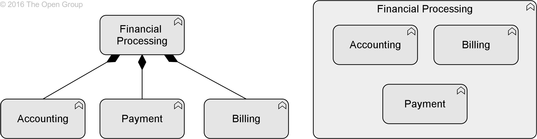
Example 2: Composition
The aggregation relationship indicates that an element groups a number of other elements.
The aggregation relationship has been inspired by the aggregation relationship in UML class diagrams. In contrast to the composition relationship, an object can be part of more than one aggregation.
An aggregation relationship is always allowed between two instances of the same element type.
In addition to this, the metamodel explicitly defines other source and target elements that may be connected by an aggregation relationship.

Figure 21: Aggregation Notation
The usual interpretation of an aggregation relationship is that whole or part of the source element aggregates the whole of the target element.
Example
The models below show two ways to express that the Customer File aggregates an Insurance Policy and Insurance Claim.
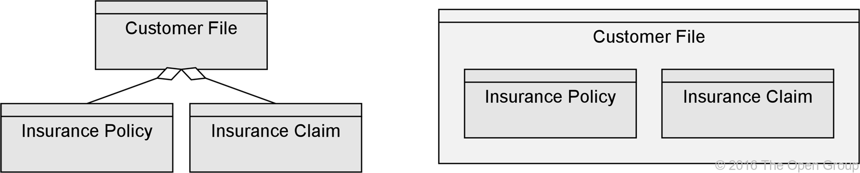
Example 3: Aggregation
The assignment relationship expresses the allocation of responsibility, performance of behavior, or execution.
The assignment relationship links active structure elements with units of behavior that are performed by them, business actors with business roles that are fulfilled by them, and nodes with technology objects. It can, for example, relate an internal active structure element with an internal behavior element, an interface with a service, or a node with a technology object. The full set of permitted relationships is listed in Appendix B.
![]()
Figure 22: Assignment Notation
In the ArchiMate framework described in Section 3.4, it always points from active structure to behavior, and from behavior to passive structure. The non-directional notation from the ArchiMate 2.1 specification and before, which shows the black ball at both ends of the relationship, is still allowed but deprecated.
As with all structural relationships, an assignment relationship can also be expressed by nesting the model elements. The direction mentioned above is also the direction of nesting; for example, a business role inside the business actor performing that role, an application function inside an application component executing that function, or an artifact inside a node that stores it.
The usual interpretation of an assignment relationship is that whole or part of the source element is assigned the whole of the target element. This means that if, for example, two active structure elements are assigned to the same behavior element, either of them can perform the complete behavior. If both active structure elements are needed to perform the behavior, the grouping element or a junction (see Section 5.4.3) can be used, and if the combination of these elements has a more substantive and independent character, a collaboration would be the right way to express this.
Example
The model in the example below includes the two ways to express the assignment relationship. The Finance active structure element is assigned to the Transaction Processing function, and the Payment Interface is assigned to the Payment Service.
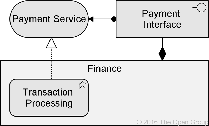
Example 4: Assignment
The realization relationship indicates that an entity plays a critical role in the creation, achievement, sustenance, or operation of a more abstract entity.
The realization relationship indicates that more abstract entities (“what” or “logical”) are realized by means of more tangible entities (“how” or “physical”). The realization relationship is used to model run-time realization; for example, that a business process realizes a business service, and that a data object realizes a business object, an artifact realizes an application component, or a core element realizes a motivation element.
![]()
Figure 23: Realization Notation
The usual interpretation of a realization relationship is that the whole or part of the source element realizes the whole of the target element. This means that if, for example, two internal behavior elements have a realization relationship to the same service, either of them can realize the complete service. If both internal behavior elements are needed to realize, the grouping element or a junction (see Section 5.4.3) can be used. For weaker types of contribution to the realization of an element, the influence relationship (Section 5.2.3) should be used.
Example
The model below illustrates two ways to use the realization relationship. A Transaction Processing function realizes a Billing Service; the Billing Data object is realized by the representation Paper Invoice.
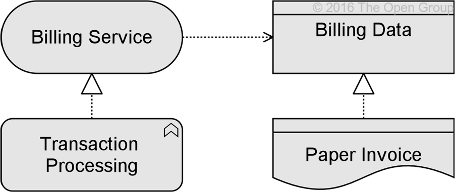
Example 5: Realization
Dependency relationships describe how elements support or are used by other elements. Three types of dependency relationship are distinguished:
• The serving relationship represents a control dependency, denoted by a solid line.
• The access relationship represents a data dependency, denoted by a dashed line.
• The influence relationship is the weakest type of dependency, used to model how motivation elements are influenced by other elements.
Note that, although the notation of these relationships resembles the notation of the dependency relationship in UML, these relationships have distinct meanings in ArchiMate notation and (usually) point in the opposite direction. One advantage of this is that it yields models with directionality, where most[2] of the arrows that represent such supporting, influencing, serving, or realizing dependencies point 'upwards' towards the client/user/business, as you can see in the layered viewpoint example in Section C.1.11. Another reason for this direction, in particular for the serving relationship, is that it abstracts from the ‘caller’ or ‘initiator’, since a service may be delivered proactively or reactively. The direction of delivery is always the same, but the starting point for the interaction can be on either end. UML’s dependency is often used to denote the latter, showing that the caller depends on some operation that is called. However, for modeling this type of initiative, the ArchiMate language provides the triggering relationship (Section 5.3.1), which can be interpreted as a dynamic (i.e., temporal) dependency. Similarly, the flow relationship is used to model how something (usually information) is transferred from one element to another, which is also a dynamic kind of dependency.
The serving relationship models that an element provides its functionality to another element.
The serving relationship describes how the services or interfaces offered by a behavior or active structure element serve entities in their environment. This relationship is applied for both the behavior aspect and the active structure aspect.
Compared to the earlier versions of this standard, the name of this relationship has been changed from ‘used by’ to ‘serving’, to better reflect its direction with an active verb: a service serves a user. The meaning of the relationship has not been altered. The ‘used by’ designation is still allowed but deprecated, and will be removed in a future version of the standard.
![]()
Figure 24: Serving Notation
The usual interpretation of a serving relationship is that the whole of the source element serves (is used by) the target element. This means that if, for example, two services serve the same internal behavior element, both of these services are needed. If two services are alternative solutions and only one of them is needed by the internal behavior element, an or junction (see Section 5.4.3) can be used.
Example
The model below illustrates the serving relationship. The Payment Interface serves the Customer, while the Payment Service serves the Pay Invoices process of that customer.
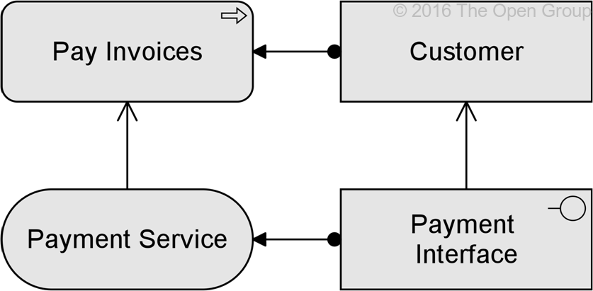
Example 6: Serving
The access relationship models the ability of behavior and active structure elements to observe or act upon passive structure elements.
The access relationship indicates that a process, function, interaction, service, or event “does something” with a passive structure element; e.g., create a new object, read data from the object, write or modify the object data, or delete the object. The relationship can also be used to indicate that the object is just associated with the behavior; e.g., it models the information that comes with an event, or the information that is made available as part of a service. The arrow head, if present, indicates the direction of the flow of information. (The access relationship should not be confused with the UML dependency relationship, which uses a similar notation.)
Note that, at the metamodel level, the direction of the relationship is always from an active structure element or a behavior element to a passive structure element, although the notation may point in the other direction to denote ‘read’ access, and in both directions to denote read-write access. Care must be taken when using access with derived relationships because the arrow on the relationship has no bearing to its directionality.
![]()
Figure 25: Access Notation
Alternatively, an access relationship can be expressed by nesting the passive structure element inside the behavior or active structure element that accesses it; for example, nesting a data object inside an application component.
The usual interpretation of an access relationship is that the whole of the target element is accessed by the source element. This means that if, for example, the same internal behavior element accesses two passive structure elements, both of these passive structure elements are needed. If two passive structure elements are, for example, alternative information sources and only one of them is needed by the internal behavior element, an or junction (see Section 5.4.3) can be used.
Example
The model below illustrates the access relationship. The Create Invoice sub-process writes/creates the Invoice object; the Send Invoice sub-process reads that object.
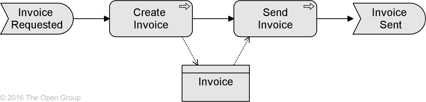
Example 7: Access
The influence relationship models that an element affects the implementation or achievement of some motivation element.
The influence relationship is used to describe that some architectural element influences achievement or implementation of a motivation element, such as a goal or a principle. In general, a motivation element is realized to a certain degree. For example, consistently satisfying the principle ‘serve customers wherever they are’ will help making the goal ‘increase market share’ come true. In other words, the principle contributes to the goal. In turn, to implement the principle ‘serve customers wherever they are’, it may be useful to impose a requirement of ‘24x7 web availability’ on some customer-facing application component. This can be modeled as a requirement that has an influence on that principle, and as an application component that in turn influences the requirement. Consistently modeling these dependencies with an influence relationship yields a traceable motivational path that explains why (in this example) a certain application component contributes to the corporate goal to ‘increase market share’. This kind of traceability supports measuring the results of Enterprise Architecture, and provides valuable information to, for example, change impact assessments.
Additional to this ‘vertical’ use of contribution, from core elements upwards to requirements and goals, the relationship can also be used to model ‘horizontal’ contributions between motivation elements. The influence relationship in that case describes that some motivation element may influence (the achievement or implementation of) another motivation element. In general, a motivation element is achieved to a certain degree. An influence by some other element may affect this degree, depending on the degree in which this other element is satisfied itself. For example, the degree in which the goal to increase customer satisfaction is realized may be represented by the percentage of satisfied customers that participate in a market interview. This percentage may be influenced by, for example, the goal to improve the reputation of the company; i.e., a higher degree of improvement results in a higher increase in customer satisfaction. On the other hand, the goal to lay off employees may influence the company reputation negatively; i.e., more lay-offs could result in a lower increase (or even decrease) in the company reputation. And thus (indirectly), the goal to increase customer satisfaction may also be influenced negatively.
The realization relationship should be used to represent relationships that are critical to the existence or realization of the target, while the influence relationship should be used to represent relationships that are not critical to the target object’s existence or realization. For example, a business actor representing a construction crew might realize the goal of constructing a building, and a requirement to add additional skilled construction workers to an already adequate crew might influence the goal of constructing the building, but also realize an additional goal of opening the building by a particular date. Moreover, an influence relationship can be used to model either:
• The fact that an element positively contributes to the achievement or implementation of some motivation element, or
• The fact that an element negatively influences – i.e., prevents or counteracts – such achievement
Attributes can be used to indicate the sign and/or strength of the influence. The choice of possible attribute values is left to the modeler; e.g., {++, +, 0, -, --} or [0..10]. By default, the influence relationship models a contribution with unspecified sign and strength.
![]()
Figure 26: Influence Notation
Example
The model below illustrates the use of the influence relationship to model the different effects of the same motivation element, Assign Personal Assistant. This has a strongly positive influence on Reduce Workload Of Employees, but a strongly negative influence on Decrease Costs.
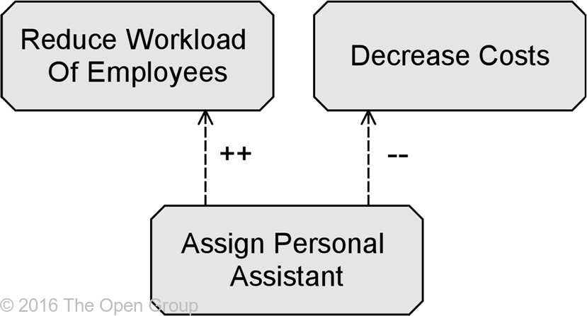
Example 8: Influence
The dynamic relationships describe temporal dependencies between elements within the architecture. Two types of dynamic relationships are distinguished:
• The triggering relationship represents a control flow between elements, denoted by a solid line.
• The flow relationship represents a data (or value) flow between elements, denoted by a dashed line.
The triggering relationship describes a temporal or causal relationship between elements.
The triggering relationship is used to model the temporal or causal precedence of behavior elements in a process. The usual interpretation of a triggering relationship is that the source element should be completed before the target element can start, although weaker interpretations are also permitted. Note that this does not necessarily represent that one behavior element actively starts another; a traffic light turning green also triggers the cars to go through the intersection.
![]()
Figure 27: Triggering Notation
Example
The model below illustrates that triggering relationships are mostly used to model causal dependencies between (sub-)processes and/or events.
![]()
Example 9: Triggering
The flow relationship represents transfer from one element to another.
The flow relationship is used to model the flow of, for example, information, goods, or money between behavior elements. A flow relationship does not imply a causal relationship.
![]()
Figure 28: Flow Notation
Example
The model below shows a Claim Assessment function, which forwards decisions about the claims to the Claim Settlement function. In order to determine the order in which the claims should be assessed, Claim Assessment makes use of schedule information received from the Scheduling function.
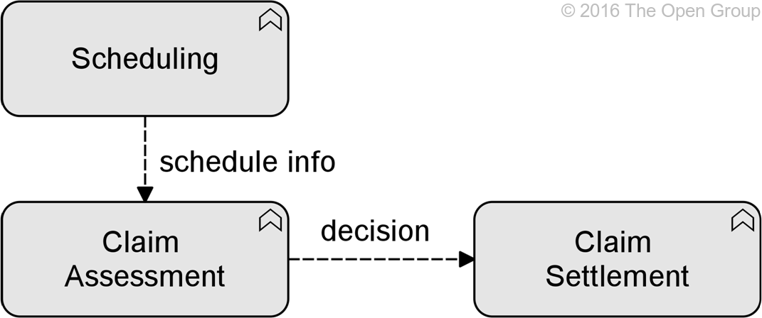
Example 10: Flow
The specialization relationship indicates that an element is a particular kind of another element.
The specialization relationship has been inspired by the generalization relationship in UML class diagrams, but is applicable to specialize a wider range of concepts. The specialization relationship can relate any instance of a concept with another instance of the same concept.
A specialization relationship is always allowed between two instances of the same element.
![]()
Figure 29: Specialization Notation
Alternatively, a specialization relationship can be expressed by nesting the specialized element inside the generic element.
Example
The model below illustrates the use of the specialization relationship for a process. In this case the Take Out Travel Insurance and Take Out Luggage Insurance processes are a specialization of a more generic Take Out Insurance process.
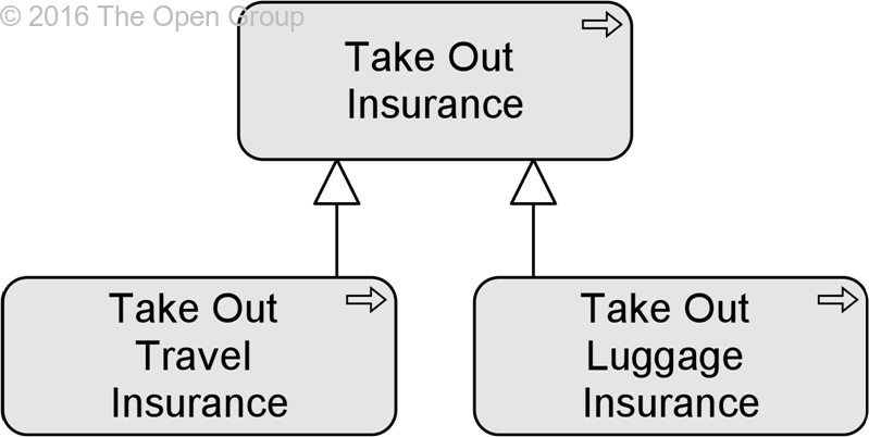
Example 11: Specialization
An association models an unspecified relationship, or one that is not represented by another ArchiMate relationship.
An association relationship is always allowed between two elements, or between a relationship and an element.
The association relationship can be used when drawing a first high-level model where relationships are initially denoted in a generic way, and later refined to show more specific relationship types. In the metamodel pictures, some specific uses of the association relationship are explicitly shown.
![]()
Figure 30: Association Notation
Example
The model illustrates a number of uses of the association relationship. It also shows an example of an association between a flow relationship and a passive structure element, to indicate the kind of information that is communicated between the two functions.
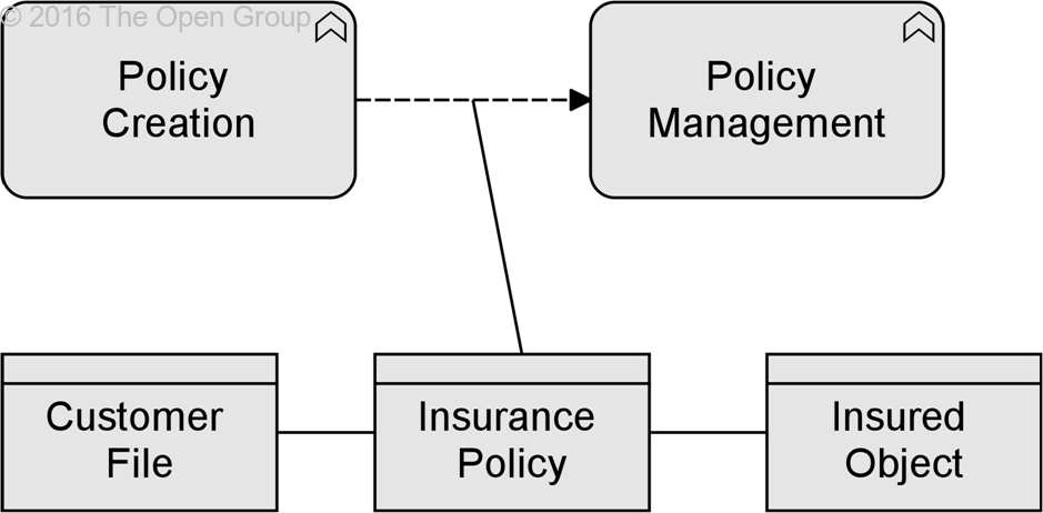
Example 12: Association
A junction is not an actual relationship in the same sense as the other relationships described in this chapter, but rather a relationship connector.
A junction is used to connect relationships of the same type.
A junction is used in a number of situations to connect relationships of the same type. A junction may have multiple incoming relationships and one outgoing relationship, one incoming relationship and multiple outgoing relationships, or multiple incoming and outgoing relationships (the latter can be considered a shorthand of two subsequent junctions).
The relationships that can be used in combination with a junction are all the dynamic relationships, as well as assignment, realization, and association. A junction is used to explicitly express that several elements together participate in the relationship (and junction) or that one of the elements participates in the relationship (or junction). A junction should either have one incoming and more than one outgoing relationships, or more than one incoming and one outgoing. It is allowed to omit arrowheads of relationships leading into a junction.
![]()
Figure 31: Junction Notation
Junctions used on triggering relationships are similar to gateways in BPMN and forks and joins in UML activity diagrams. They can be used to model high-level process flow. A label may be added to outgoing triggering relationships of a junction to indicate a choice, condition, or guard that applies to that relationship. Such a label is only an informal indication. No formal, operational semantics has been defined for these relationships, because implementation-level languages such as BPMN and UML differ in their execution semantics and the ArchiMate language does not want to unduly constrain mappings to such languages.
Examples
In the model below, the junction in the model is used to denote that the Sales and Finance functions together realize the Invoicing service.
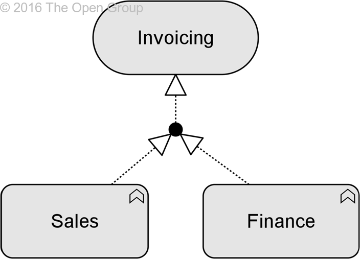
Example 13: (And) Junction
In the model below, the or junction is used to denote a choice: process Assess Request triggers either Accept Request or Reject Request. (The usual interpretation of two separate triggering relations, one from Assess Request to Accept Request and one from Assess Request to Reject Request, is that Assess Request triggers both of the other processes.)
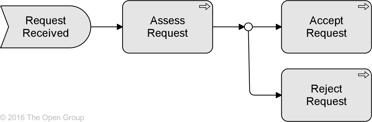
Example 14: Or Junction
Table 3 gives an overview of the ArchiMate relationships with their definitions.
Table 3: Relationships
|
Structural Relationships |
Notation |
|
|
Composition |
Indicates that an element consists of one or more other elements. |
|
|
Aggregation |
Indicates that an element groups a number of other elements. |
|
|
Assignment |
Expresses the allocation of responsibility, performance of behavior, or execution. |
|
|
Realization |
Indicates that an entity plays a critical role in the creation, achievement, sustenance, or operation of a more abstract entity. |
|
|
Dependency Relationships |
Notation |
|
|
Serving |
Models that an element provides its functionality to another element. |
|
|
Access |
Models the ability of behavior and active structure elements to observe or act upon passive structure elements. |
|
|
Influence |
Models that an element affects the implementation or achievement of some motivation element. |
|
|
Dynamic Relationships |
Notation |
|
|
Triggering |
Describes a temporal or causal relationship between elements. |
|
|
Flow |
Transfer from one element to another. |
|
|
Other Relationships |
Notation |
|
|
Specialization |
Indicates that an element is a particular kind of another element. |
|
|
Association |
Models an unspecified relationship, or one that is not represented by another ArchiMate relationship. |
|
|
Junction |
Used to connect relationships of the same type. |
|
This section presents a number of rules to derive indirect relationships between elements in a model, based on the modeled relationships. This makes it possible to abstract from intermediary elements that are not relevant to show in a certain model or view of the architecture, and supports impact analysis.
It is important to note that all these derived relationships are also valid in the ArchiMate language. These are not shown in the metamodel diagrams included in this standard because this would reduce the legibility of them. However, the tables in Appendix B show all permitted relationships between two elements in the language.
Note that these derivation rules do not work on relationships with grouping, or between core elements and other elements such as motivation, strategy, or implementation and migration elements, with the exception of the realization and influence relationships.
The structural and dependency relationships can be ordered by ‘strength’. Structural relationships are ‘stronger’ than dependency relationships, and the relationships within these categories can also be ordered by strength:
• Influence (weakest)
• Access
• Serving
• Realization
• Assignment
• Aggregation
• Composition (strongest)
Part of the language definition is an abstraction rule that states that two relationships that join at an intermediate element can be combined and replaced by the weaker of the two.
If two structural or dependency relationships r:R and s:S are permitted between elements a, b, and c such that r(a,b) and s(b,c), then a structural relationship t:T is also permitted, with t(a,c) and type T being the weakest of R and S.
For the application of this rule, it is assumed that the assignment relationship has a direction (as indicated by the role names in the metamodel figures), as defined in Section 5.1.3.
Transitively applying this property allows us to replace a ‘chain’ of structural relationships (with intermediate model elements) by the weakest structural relationship in the chain. For a more formal description and derivation of this rule the reader is referred to [11]. Note that the resulting derived relationship is a potential relationship, which is what is needed for impact analysis. To derive certain relationships, other derivation rules are needed, which are beyond the scope of this standard.
An example is shown in the figure below: assume that the goal is to omit the functions, sub-functions, and services from the model. In this case, an indirect serving relationship (the relationship labeled Derived Relationship (thick arrow on the right) can be derived from Financial application to the Invoicing and collections process (from the chain assignment – composition – realization – serving).
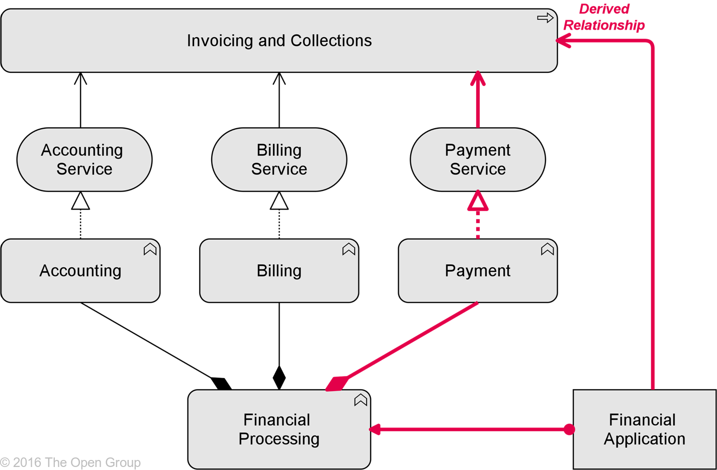
Example 15: Derived Structural and Dependency Relationship
Note: In deriving the relationship tables in the appendix, a distinction has been made between artifacts realizing active structure elements and those realizing passive structure elements, to avoid deriving undesirable relationships.
For the two dynamic relationships, the following rules apply:
• If there is a flow relationship r from element a to element b, and a structural relationship from element c to element a, a flow relationship r can be derived from element c to element b.
• If there is a flow relationship r from element a to element b, and a structural relationship from element d to element b, a flow relationship r can be derived from element a to element d.
These rules can be applied repeatedly. Informally, this means that the begin and/or endpoint of a flow relationship can be transferred ‘backward’ in a chain of elements connected by structural relationships. The example below shows two of the possible flow relationships that can be derived with these rules, given a flow relationship between the two services.
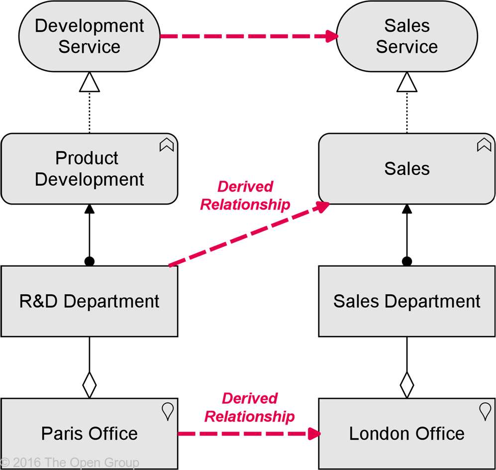
Example 16: Derived Flow Relationships
This rule also applies for a triggering relationship, but only in combination with an assignment relationship (not with other structural relationships):
• If there is a triggering relationship r from element a to element b, and an assignment relationship from element c to element a, a triggering relationship r can be derived from element c to element b.
• If there is a triggering relationship r from element a to element b, and an assignment relationship from element d to element b, a triggering relationship r can be derived from element a to element d.
Moreover, triggering relationships are transitive:
• If there is a triggering relationship from element a to element b, and a triggering relationship from element b to element c, a triggering relationship can be derived from element a to element c.
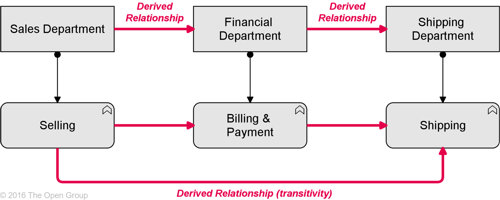
Example 17: Derived Triggering Relationships
Downloads of the ArchiMate documentation, are available under license from the ArchiMate information web site. The license is free to any organization wishing to use ArchiMate entirely for internal purposes. A book is also available (in hardcopy and pdf) from The Open Group Bookstore as document C162.