The previous chapters have presented the concepts to model the Business, Application, and Technology Layers of an enterprise. However, a central issue in Enterprise Architecture is business-IT alignment: how can these layers be matched? This chapter describes the relationships that the ArchiMate language offers to model the link between business, applications, and technology.
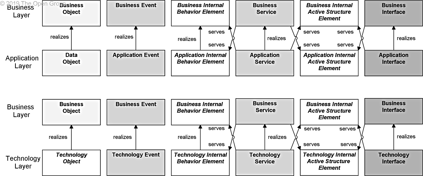
Figure 104 shows the relationships between the Business Layer, the Application Layer, and the Technology Layer elements. There are two main types of relationships between these layers:
1. Serving relationships; for example, between application service and the different types of business behavior elements, and between application interface and business role; vice versa, serving relationships between business service and application behavior elements, and between business interface and application component. These relationships represent the behavioral and structural aspects of the support of the business by applications.
2. Realization relationships; for example, from an application process or function to a business process or function, or from a data object or a technology object to a business object, to indicate that the data object is a digital representation of the corresponding business object, or the technology object is a physical representation of the business object.
In addition, there may be an aggregation relationship between a product and an application or technology service, and a data or technology object, to indicate that these services or objects can be offered directly to a customer as part of the product.
Figure 104: Relationships Between Business Layer and Application and Technology Layer Elements
Note: This figure does not show all permitted relationships; there are indirect relationships that can be derived, as explained in Section 5.7.
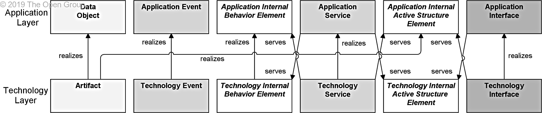
Figure 105 shows the relationships between Application Layer and Technology Layer elements. There are two types of relationships between these layers:
1. Serving relationships, between technology service and the different types of application behavior elements, and between technology interface and application component; vice versa, serving relationships between application service and technology behavior, and application interface and node. These relationships represent the behavioral and structural aspects of the use of technology infrastructure by applications and vice versa.
2. Realization relationships from technology process or function to application process or function, from technology object to data object, to indicate that the data object is realized by, for example, a physical data file, from technology object to application component, to indicate that a physical data file is an executable that realizes an application or part of an application. (Note: In this case, an artifact represents a “physical” component that is deployed on a node; this is modeled with an assignment relationship. A (logical) application component is realized by an artifact and, indirectly, by the node on which the artifact is deployed.)
Figure 105: Relationships Between Application Layer and Technology Layer Elements
Note: This figure does not show all permitted relationships; there are indirect relationships that can be derived, as explained in Section 5.7.
Due to the derived relationships that are explained in Section 5.7, it is also possible to draw relationships directly between the Business and Technology Layers. For example, if a business object is realized by a data object, which in turn is realized by a technology object, this technology object indirectly realizes the business object.
Example 34 shows how the cross-layer relationships integrate the different layers, and how this can be depicted in one view. It also shows how the optional notation with letters in the upper-left corner is used to distinguish between layers.
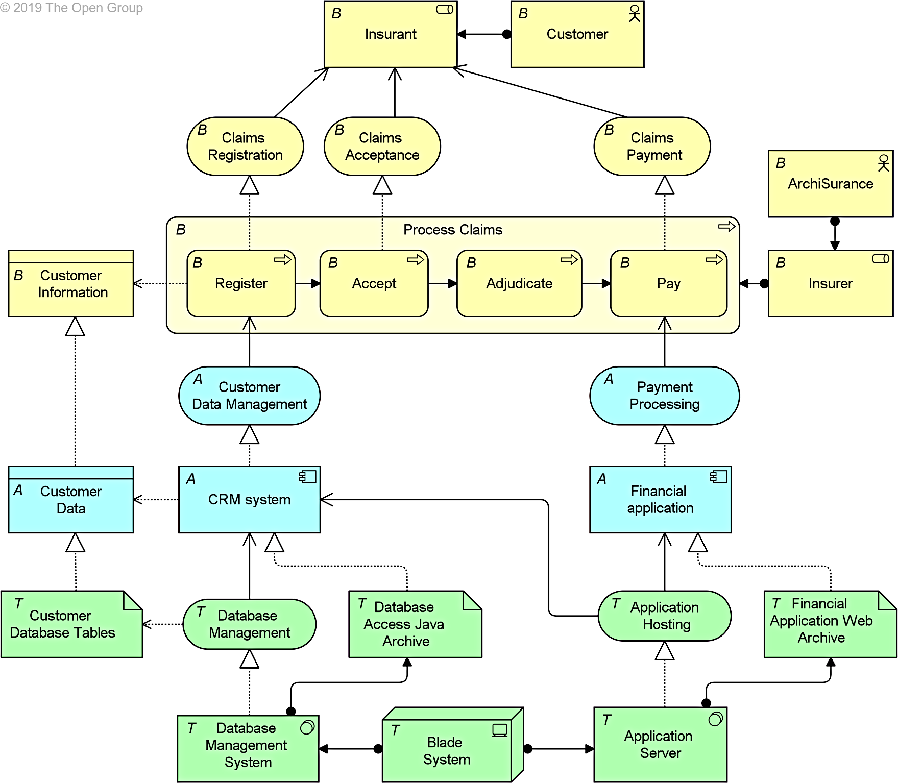
Example 34: Cross-Layer Relationships
Downloads of the ArchiMate documentation are available under license from the Download link within the ArchiMate information web site. The license is free to any organization wishing to use ArchiMate documentation entirely for internal purposes. A book is also available from The Open Group Library as document C197.