| You are here: | ||
| <<< Previous | Home | Next >>> |
This chapter explains the concept of building blocks and contains a fictional example illustrating building blocks in architecture.
This section is intended to explain and illustrate the concept of building blocks in architecture.
Following this overview, there are three main parts:
This section is an introduction to the concept of building blocks.
This subsection describes the characteristics of building blocks. The use of building blocks in the ADM is described separately in Building Blocks and the ADM .
Building blocks have generic characteristics as follows:
A building block is therefore simply a package of functionality defined to meet business needs. The way in which functionality, products, and custom developments are assembled into building blocks will vary widely between individual architectures. Every organization must decide for itself what arrangement of building blocks works best for it. A good choice of building blocks can lead to improvements in legacy system integration, interoperability, and flexibility in the creation of new systems and applications.
Systems are built up from collections of building blocks, so most building blocks have to interoperate with other building blocks. Wherever that is true, it is important that the interfaces to a building block are published and reasonably stable.
Building blocks can be defined at various levels of detail, depending on what stage of architecture development has been reached.
For instance, at an early stage, a building block can simply consist of a grouping of functionality such as a customer database and some retrieval tools. Building blocks at this functional level of definition are described in TOGAF as Architecture Building Blocks (ABBs). Later on, real products or specific custom developments replace these simple definitions of functionality, and the building blocks are then described as Solution Building Blocks (SBBs).
More detail on each of these aspects of building blocks is given below.
Architecture Building Blocks (ABBs) relate to the Architecture Continuum (The Architecture Continuum), and are defined or selected as a result of the application of the ADM.
ABBs:
ABB specifications include the following as a minimum:
Solution Building Blocks (SBBs) relate to the Solutions Continuum (The Solutions Continuum), and may be either procured or developed.
SBBs:
SBB specifications include the following as a minimum:
This section focuses on the use of building blocks in the ADM. General considerations and characteristics of building blocks are described in Introduction to Building Blocks .
An architecture is a set of building blocks depicted in an architectural model, and a specification of how those building blocks are connected to meet the overall requirements of an information system.
The various building blocks in an architecture specify the services required in an enterprise-specific system.
There are some general principles underlying the use of building blocks in the design of specific architectures:
The process of identifying building blocks includes looking for collections of functions which require integration to draw them together or make them different:
In the early stages and during views of the highest-level enterprise, the building blocks are often kept at a broad integration definition. It is during these exercises that the services definitions can often be best viewed. As implementation considerations are addressed, more detailed views of building blocks can often be used to address implementation decisions, focus on the critical strategic decisions, or aid in assessing the value and future impact of commonality and re-usability.
The process of building block definition takes place gradually as the ADM is followed, mainly in Phases A, B, C, and D. It is an iterative process because as definition proceeds, detailed information about the functionality required, the constraints imposed on the architecture, and the availability of products may affect the choice and the content of building blocks.
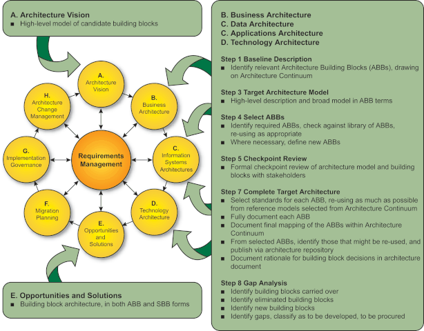
The key parts of the ADM at which building blocks are designed and specified are summarized below.
The major work in these steps consists of identifying the ABBs required to meet the business goals and objectives. The selected set of ABBs is then refined in an iterative process to arrive at a set of SBBs which can either be bought off-the-shelf or custom developed.
The specification of building blocks using the ADM is an evolutionary and iterative process. The key phases and steps of the ADM
at which building blocks are evolved and specified are summarized below, and illustrated in Key Phases/Steps of ADM at which Building Blocks are
Evolved/Specified .

In Phase A the earliest building block definitions start as relatively abstract entities within the Architecture Vision.
In Phases B, C, and D building blocks within the Business, Data, Applications, and Technology Architectures are evolved to a common pattern of steps:
Finally, in Phase E the building blocks become more implementation-specific as SBBs, and their interfaces become the detailed architecture specification. The output of Phase E is the building block architecture, both in ABB (i.e., functionally defined) and SBB (i.e., product-specific) forms.
The minimum contents of an ABB specification and a SBB specification are described in Introduction to Building Blocks .
Defining and developing the context for a set of building blocks takes place at two levels:
Defining and developing an actual set of building blocks also takes place at two levels:
Working through the four levels is an iterative process. Iteration between the Four Levels of Modeling shows how considerations at any level can result
in change at any or all of the other levels.
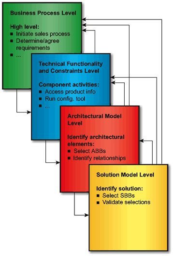
The Business Process level of definition takes place in Phases A and B of the ADM.
The Technical Functionality and Constraints level work happens early in Phases B, C, and D, once the characteristics of the current system have been established. At that stage it is possible to identify the constraints imposed on new architecture work by the legacy of the old system (the baseline).
The Architectural Model and Solution Model levels consist of work done later in Phases B, C, and D, the Target Architecture steps of each phase, and Phase E. The Architectural Model work is mostly done when taking different views of the architecture, and the Solution Model work in Phase E, where selection of products and projects takes place.
To show how building block definition happens in practice, the remainder of this chapter consists of a fictional worked example. In this fictional example much detail has been left out in order to emphasize the process.
This and the following sections provide a detailed worked example showing how building block context is captured, how building blocks are identified, and how building blocks are defined when executing the major steps of the ADM.
The levels of modeling within the ADM are explained in Building Blocks and the ADM , and the example follows the structure of modeling explained there:
In this example, a fictional company called XYZ Manufacturing has decided to improve the efficiency of its mobile sales force by replacing paper-based configuration and ordering systems with an IT solution.
The XYZ team have already done the preliminary stages of describing their existing system and reviewing it from a number of different viewpoints, and as a result have established a number of goals and objectives for the new system.
The principal goal is to give the sales force in the field direct access to the sales process back at base. This will allow sales staff to create and verify the product configuration, to check the price and availability of the goods, and to place the order while actually with the customer.
Other stages of the sales process - such as initiating the sale and determining the customer requirements - are considered to be outside the scope of this example.
The inputs to ADM Phase B are:
The outputs of this step are:
As a preliminary to this step it is necessary to define the scope of activity, including what is in scope, what is out of scope, what the limits are, and what the financial envelope is. Within this step fall defining the business process, recording the assumptions made, and developing any new requirements. The information collected is used to gauge the current system and to determine the return on investment of potential changes. Use-cases are a useful tool in this step to describe the business processes and they can be used to do a sanity check against the resulting architecture.
The business goals driving improvements in the sales process were:
In this example, financial and time constraints and business return have not been dealt with in detail, but normally these constraints would be used to guide the process along the entire way to avoid over-engineering or "creeping elegance". The architect should especially look at these constraints whenever iterating between steps. Also not shown in this example are the use-case scenarios. However, the process described below does include participants, or actors, of the use-case with brief descriptions of their roles in Use-Case Table of Sales Process .
For the sake of brevity in this example, it is assumed that the scope of the architectural work would not extend beyond the sales arena, and that the proposed solutions fit within the financial and time constraints imposed by XYZ.
The assumptions made by the XYZ architect during Phase B are:
The relevant business process in scope of this example in the XYZ company is the customer-facing portion of the sales process and the supporting systems. This sales process consists of the following steps:
The following use-case table represents participants (sometimes referred to as "actors" in use-cases) in the rows, steps of the business process in the columns, and roles in the cells. Note that this is an example, and it is not intended to be accurate, but rather demonstrative. Constructing a use-case table is a comparatively small effort that will ultimately enhance the speed and quality of the resulting architecture.
The meanings of the various acronyms used in the table, and in subsequent figures, are listed below:
|
|
|
2:Discuss |
3:Create |
4:Verify |
|
|
|
|
|---|---|---|---|---|---|---|---|---|
|
|
1:Initiate |
Reqmts |
Config |
Config |
5:Price |
6:Confirm |
7:Order |
8:Accept |
|
Sales |
Greets |
Listens. |
Represents options with different capabilities. |
Accesses ICSys and SchSys and presents availability to customer. |
Accesses price system and presents price to customer. |
Presents |
Accesses order system. |
Presents |
|
Customer |
Accepts sales person. |
Discusses problems/ |
Listens and decides on options based on capabilities. |
Accepts or |
|
Accepts or |
|
Signs or |
|
Sales |
|
|
Interacts with configurator. |
Interacts with ICSys and SchSys. |
Interacts with price system. |
|
Interacts with order system and receives fax response. |
|
|
Sales |
|
|
Provides central information processing. |
|
|
|
|
|
|
Sales |
|
|
Provides local information processing. |
|
|
|
|
|
|
ProdConfig |
|
|
Presents configs to sales person per needs, providing capabilities. |
|
|
|
|
|
|
ICSys |
|
|
|
Provides availability. |
|
|
|
|
|
SchSys |
|
|
|
Provides delivery date. |
|
|
|
|
|
$Sys |
|
|
|
|
Provides price information on a config. |
|
|
|
|
OrderSys |
|
|
|
|
|
|
Processes order and sends fax of order to sales person's laptop. |
|
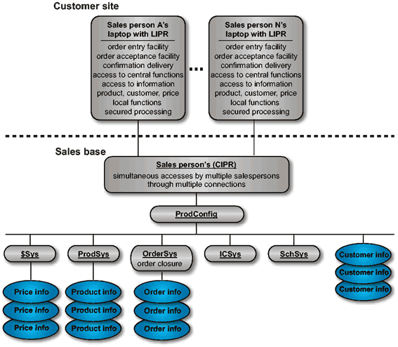
Steps 1, 2, 6, and 8 are not within scope of the architecture work since the only participants involved are humans. The other steps are considered within scope since there are computing components involved in supporting the sales process. Note the computing participants are the first set of identified candidate building blocks - Business Process-Driven List.
During Phase A, the business goals were developed into more detailed business requirements, and these were:
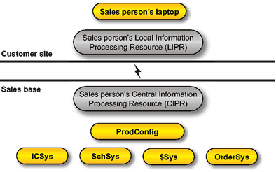
A very simplified view of the candidate building blocks required to support the business process with an idea of location is provided below. This model was built from elements of the above table.
The objective of the first step in Phases B, C, and D of the ADM is to build a high-level description of the characteristics of the current system, re-usable building blocks from the current system, the technical functionality needed to address the business problem, and to identify additional constraints. This is necessary as the description documents the starting point for architectural development and lists the interoperability issues that the final architecture will have to take into account. Potential re-usable building blocks may be contained in the existing environment. They are identified in this step.
The best approach is to describe the system in terms already used within the organization. A reliable picture can be built up of the business functions served and the platforms which support those functions. Gather and analyze only that information that allows informed decisions to be made regarding the Target Architecture.
The inputs to this step are:
The essential outputs from this activity are:
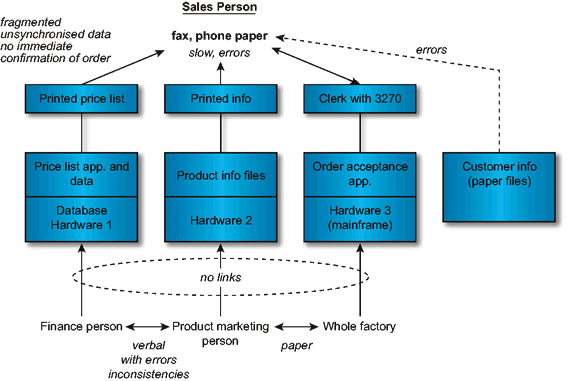
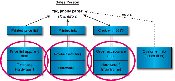
The key input to this step is the existing architecture. In this example, a depiction of an existing architecture is shown in
XYZ Existing Architecture .
Additionally depicted in this architecture model are pointers to existing problems with the existing architecture. These pointers
are used by the architect to determine where existing components are failing, and where existing systems can be
re-used.
It is necessary to record existing strategic decisions about the existing architectural and technological issues such as:
The next step consists of restating the business process, considering what functionality will be required, and deciding what constraints apply. Decisions at this stage are not definitive, but act as input for the following steps and iterations.
The architects of XYZ identified the following pieces of technical functionality as necessary to support the business processes. This list was produced using standard brainstorming techniques.
Also in the brainstorming session, some assumptions were made and therefore must be documented as they should be used throughout the process:
One constraint was put on the development because XYZ already had systems in place to support the sales process:
The above model is scrutinized and questions are asked about the functionality that could be provided by the existing system.
Candidate Building Blocks from the
Baseline-Driven List depicts the set of candidate building blocks from the existing system, resulting from this
question.
In Phases B, C, and D a number of different architectural architecture views are considered and used to build up a model of the new architecture. At XYZ, the
Architectural Model level was developed in the following steps:
In executing Step 1, the existing architecture was assessed:

Notice how in Existing Architecture
in TOGAF Terms and Future
Architecture of Functions the legacy systems supporting the price list, product info, and order acceptance applications are
easy to handle as monolithic building blocks. Augmented Future Architecture of Functions , Representation of XYZ SOAP System , and Services Map show they can be connected to new building blocks using
adapters.
In Step 2, the function view was examined based upon what the system was intended to do, and how it should behave. The function
view is depicted in Future
Architecture of Functions . Note that the inventory control and scheduling system are not
covered.
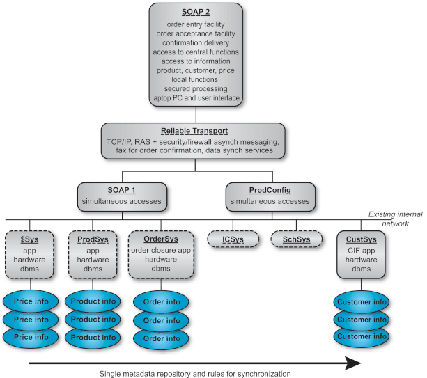
In executing Step 2, a view of the future architecture was created by processing the technical functionality that must be provided and by:
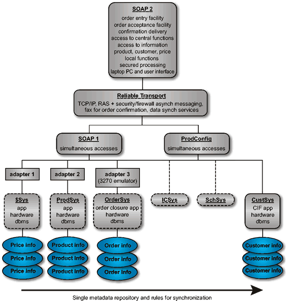
Augmented Future Architecture of
Functions shows how the constraints identified in the earlier technical functionality and constraints work have been
incorporated. It was necessary to retain the existing systems for order handling and product information. The initial constraint
list also included retaining the existing system for customer information, but this was overridden by the need to improve the
quality of the sales process and a new system is proposed to deal with this. Return on investment is the driving force behind the
decision to retain the existing system for price data. Quality problems with the price system highlighted in XYZ Existing Architecture will be resolved
through a single metadata definition and rules for synchronization as shown in Future Architecture of Functions . These legacy systems are
integrated into the new SOAP (Sales Order Application) by developing adapter software. The following describes the SOAP
application.
To ensure that building blocks are as re-usable as possible, detailed information is needed about the building block. For this reason it is helpful to take views of individual building blocks and not just of the complete system. For the maximum benefit, it may be necessary to take views of both ABBs and SBBs.
It is the responsibility of the architect to foresee the integration of any application with the rest of the enterprise regardless of the isolated position of the application today. This future integration is facilitated by complete definition of building blocks. It is the responsibility of the business unit to implement in accordance with the rules of the architecture.
Step 3 consists of creating an architecture model of building blocks. Augmented Future Architecture of Functions depicts a future architecture model of
functions, but does not express the relationships and interfaces between the elements in the architecture model. As the
architectural development process continues, it becomes important to define a manageable granularity for building blocks and to
fully define their linkages. Without this work there is no guarantee of interoperability between the various building blocks
chosen.
We have identified two lists of candidate building blocks in the above steps. Prior to building a model of building blocks, these lists are processed and some candidates become recommended building blocks.
|
Candidate Building Blocks: |
Candidate Building Blocks: |
|---|---|
|
Business Process-Driven List |
Baseline-Driven List |
|
Sales person's laptop |
Price list application, data, and platform |
|
Sales person's CIPR |
Product information and platform |
|
Sales person's LIPR |
Order acceptance application, data, and platform |
|
ProdConfig |
|
|
ICSys |
|
|
SchSys |
|
|
$Sys |
|
|
OrderSys |
|
The process of identifying building blocks includes looking for collections of functions which require integration to draw them together or make them different.
First, it is recommended that the candidate building blocks from list B be selected as building blocks because they are re-usable legacy items. With these, a building block containing all the adapters is identified given the affinity of similar logic; e.g., providing the network adapter functionality on behalf of all the legacy applications.
Next a network building block appears to be required as it is a new network that must be built or purchased and is independent of the applications implemented. It itself can be a re-usable building block for other applications.
The laptop with the SOAP2 application is identified as a building block because it is a modular pack of functionality specially built with applications and data tightly integrated for the mobile sales force. However, a RAS-capable firewall was also identified as a separable building block.
The new customer information system is also identified as a re-usable building block given its applicability across applications past, new, and future. The SOAP1 and configuration systems were identified as two additional building blocks.
We depict the ABBs at a high-level in Representation of XYZ SOAP System .
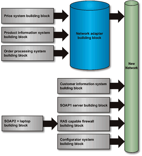
Representation of XYZ SOAP
System presents a relationship view of the system. Compare this with Augmented Future Architecture of Functions , a functional view, to see how different
diagrammatic views of the same system can be used to show different
things.
In executing Step 3, the future architecture was created by processing the technical functionality that must be provided and:
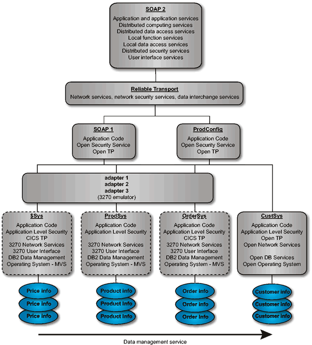
Step 4 is to select the services portfolio required per building block. Services Map depicts the services mapped to component in the architecture
model.
Step 5 in the process is to confirm that the architecture supports the business goals and objectives. This is a relatively subjective task of answering the questions developed in Step 1. In this example, we did not establish a set of questions that would be used to test the architecture, but such questions (and how to pose them in light of the architecture) could easily be envisioned. For example, one question could be: "Does the architecture prohibit the immediate processing of an order by a customer?" which would be answered "no" in our case above.
The use-cases developed earlier are a handy tool to test the completeness and applicability of the architecture and its building blocks.
Building block specifications should be recorded in detail. An example of a building block specification document is given in Customer Information System Building Block Specification .
Where an enterprise architecture exists or is being developed, it may be valuable at this point to review the new set of building blocks. Anything of benefit to the wider enterprise should be abstracted back to an architectural level and then fed back into the enterprise architecture development process.
Step 8 is to conduct a gap analysis, and is not covered in this example.
This system is put in place of the existing paper-based customer information system to support the goal of improving the speed and quality of order closure. It shields the database from the complexity of the many applications looking at it but it contains an architectural break-point which could be used later on to make the database itself accessible to other applications.
The interfaces selected must go through an internal approval process modeled on the interface adoption criteria of The Open Group. This means that all specifications must be or become part of the corporate Standards Information Base (SIB).
|
Functionality |
|
Interfaces - APIs, |
|
|---|---|---|---|
|
Category |
Functionality |
Formats, & Protocols |
Product or Project |
|
CIF Application Code |
Respects metadata repository spec |
User-defined |
User-defined |
|
|
Implements business rules |
User-defined |
User-defined |
|
|
Has remote access by SOAP and configurator |
DCE RPC |
See SIB |
|
|
Uses SQL |
ANSI SQL |
|
|
|
|
CLI |
|
|
|
Uses UNIX |
UNIX 95 |
|
|
Open DB Services |
Relational |
Codd |
|
|
|
Supports concurrent access |
Codd |
|
|
|
Offers SQL |
ANSI SQL |
|
|
Open Security Services |
Single sign-on |
|
|
|
|
Authorization |
DCE |
|
|
|
Authentication |
DCE |
|
|
|
Integrity |
|
|
|
|
Audit |
DCE |
|
|
|
Non-repudiation |
|
|
|
Open Operating System |
UNIX |
UNIX 95 |
|
|
Network Services |
Existing internal network |
User-defined |
User-defined |
|
Open TP |
Multiple concurrent access |
The Open Group XA |
|
|
|
Load leveling |
|
|
|
+Performance |
50 enquiries per second |
|
|
|
+Manageability |
Online software update |
|
|
|
|
Service-level data provision |
DMTF Spec |
|
|
|
Integration into enterprise management system |
TBD |
|
|
+Availability |
24 by 7 by 52 |
|
|
|
Building |
|
Required |
Named Used |
|---|---|---|---|
|
Block Name |
Owner |
Functionality |
Interfaces |
|
Enterprise Management |
Corporate IT |
Service-level data |
|
|
System |
|
handling |
|
|
|
|
Integration - TBD |
|
|
Enterprise Network |
Corporate IT |
|
|
|
CIF System |
Marketing |
|
|
|
Policy |
Entity |
Remarks |
|---|---|---|
|
Security |
Corporate admin |
|
|
Audit |
Corporate admin |
|
|
Development and deployment |
Corporate IT |
|
|
Metadata definition |
Corporate IT |
|
|
Data quality |
Corporate IT |
|
|
IT architecture |
Corporate IT |
|
|
Corporate SIB |
Corporate IT |
This is linked to The Open Group SIB. |
This is the step where projects are identified, ranked, and selected.
The steps illustrated above have laid the foundation for this analysis. Augmented Future Architecture of Functions , for instance, shows the SOAP applications,
the reliable transport, the adapters, and the new customer information system as potential
projects.
In ADM Phases F to G, the choice of building blocks may be affected by outside events, such as a change in the availability of products. They can also affect and be affected by issues such as the cost of retraining users during migration from one product to another. Perhaps the most important impact though is the effect that building block choice can have on other work in progress within an organization. This section shows how a diagrammatic representation of the building blocks in a system can be used to identify or prioritize future projects.
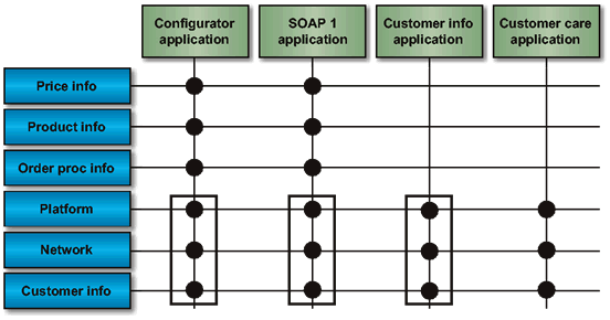
An important benefit of defining the building blocks and their linkages is that it becomes possible to pick out re-usable
components in the architecture. The best way to do this is to draw up a matrix of the building blocks used in an architecture and
the applications that use them. Such a matrix for a simple subset of the XYZ case is shown in Simple Component/Application Matrix
.
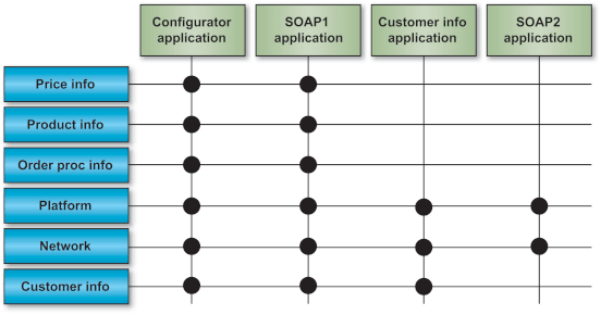
Careful ordering of the building blocks in the left-hand column allows the architect to identify subsets of functionality common
to a number of applications. Identifying Common Functionality shows such a subset. In this case the subset of platform, network, and customer
information database gives a strong indication that the configurator, SOAP1, and customer information applications should be hosted
on the same platform.
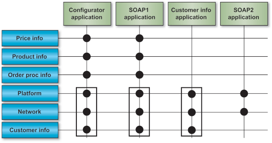
Such identifiable subsets of building blocks also serve another purpose, which is that they can draw attention to opportunities for component re-use. If in the future XYZ decides to implement a customer care system, adding that into the matrix reveals that there would be significant advantages to building the customer care system on the same building blocks used for the configurator, SOAP1, and customer information applications.
The key to success in working with building blocks is to establish a useful level of granularity. Too much detail in the chosen
set of building blocks will make the architecture unworkable, while too coarse a level of detail will make the work valueless.
return to top of page
The TOGAF document set is designed for use with frames. To navigate around the document:
Downloads of the TOGAF documentation, are available under license from the TOGAF information web site . The license is free to any organization wishing to use TOGAF entirely for internal purposes (for example, to develop an information system architecture for use within that organization). A hardcopy book is also available from The Open Group Bookstore as document G063 .