This chapter contains examples of applying the Reference Model to real-world scenarios.
Most often in current practice, the backup is of files or file systems.
However, the concept of backing up an application; e.g., a database,
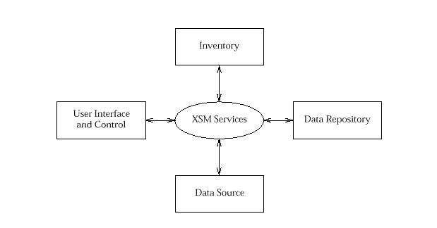
Let us look at the major components that we might expect to find in a typical backup system. The most obvious component is some form of user interface which an administrator can use to initiate the backup or restoration processes. This interface would allow the user to select the data to be backed up or restored. Such a selection might be on the basis of date or name, for example. In order for a backup process to be useful there must be some component of the system which provides the repository for the backed-up data. Frequently this will be some for of magnetic tape or perhaps optical disk. Of course, there would be no point in having a backup system at all without the fundamental component of some form of data store to be backed up! Although at first sight it may appear that this is all that is required in a backup system, anyone who has had experience with managing the backup of large amounts of data will recognise the need for one other component: an inventory. Keeping track of which data is backed up to where is a significant administrative burden, so this task needs to be substantially automated in any reasonably featured backup system.
So, there are four basic components of our backup system:

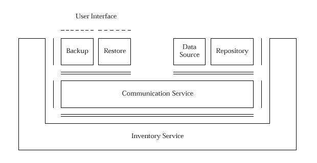
So, how does this relate the management reference model as shown in

The representation of the Inventory Service in the diagram illustrates the use of the Inventory Service. It is probable that such a service would also require to be managed, in which case the Inventory Service would appear in the Reference Model as a Managed Object. Such duality of purpose is well supported by the object-oriented techniques used to specify the Reference Model.
There is considerable power in being able to define new Managed Objects to represent completely new Resources that represent the synthesis of Resources represented by other Managed Objects, thus providing different aggregations perhaps more suited to the needs of human users.
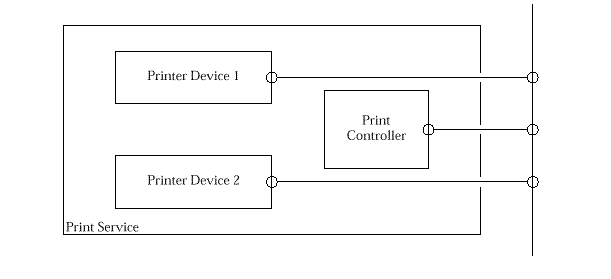
For example, consider a print room with the following equipment: two intelligent printers, a microcomputer serving as a print controller, all connected to a local area network drops.

The printers provide management access to a few attributes such as number of print jobs processed (since reset), number of queued jobs, names and sizes of the queued jobs and the currently active job. The print controller might offer a LAN service that accepts print requests and then queues the print jobs to the printers according to certain policies.
Ignoring the network for the moment, it is not difficult to imagine each of the printers and the controller being encapsulated as Managed Objects for the purpose of management. However, one may consider a new virtual entity representing the print service as implemented by the devices in the print room. Such an object is virtual in that there is no single object that is implemented in the network. However, from a Manager's perspective there is a print service and there is an obvious desire to be able to manage this service as though it existed as a single Managed Object. Such an aggregation can be defined as a new Managed Object with its own methods. The new methods would be implemented by invoking the appropriate methods against the real Resources, and synthesize the results according to the aggregation representing the complete print service.
Note the positioning of the Managed Object in the basic
reference model in
| Contents | Next section | Index |