Previous section.
Systems Management: Topology Service
Systems Management: Topology Service
Copyright © 1997 The Open Group
Topology Service Overview
The Topology Service provides
a general, distributed service for storing and
querying topological associations between objects.
The Topology Service is extensible to
handle any developer-defined topologies,
including, for example, those found among users and
computer systems,
any variety of networks, the hardware arrangements of computing
devices, I/O cards and peripherals, or shared software
and the departments that manage its use.
The Topology Service is highly useful in the handling of management problems, as it removes most of the burden applications have in storing, manipulating and querying associations
among the resources being managed. This not only reduces application development cost, it also exposes a key
integration point for applications: a rendezvous point for determining how managed
resources are organized, configured, or connected, and for how separate, underlying aspects
of the managed environment blend together to form the resources administrators manage.
Major operational goals pertaining to management that the Topology
Service addresses include:
-
the provision of an environment in which applications can integrate
with one another via topological data through consistent paradigms
-
the enabling of scalable solutions,
whereby an application can usefully participate
in managing environments that range in size from an
order of hundreds up to an order of millions objects
-
the ability to establish new associations among
objects without affecting the semantics
or implementations of those objects.
The Topology Service is configurable and extensible. It allows
applications to define what constitutes valid associations that characterize
a particular topology. This is done by specifying the rules
that the associations must obey which the Topology Service will then
enforce. The Topology Service then provides storage of the
associations and querying capabilities for retrieval.
High-level Architectural View
High-level Architcture View of Topology Service
shows the major components of a Topology
Service being submitted for standardization. These are:
-
Semantics Manager API
which is used by a client to define the topological rules which
form the semantics for a given topology
-
Data Manager API
which is used by a client to populate the Topology Service with
associations that conform to the semantics of previously-defined topology rules
-
Query Manager API
which is used by a client to retrieve topological data based on
registered (and sharable) queries.
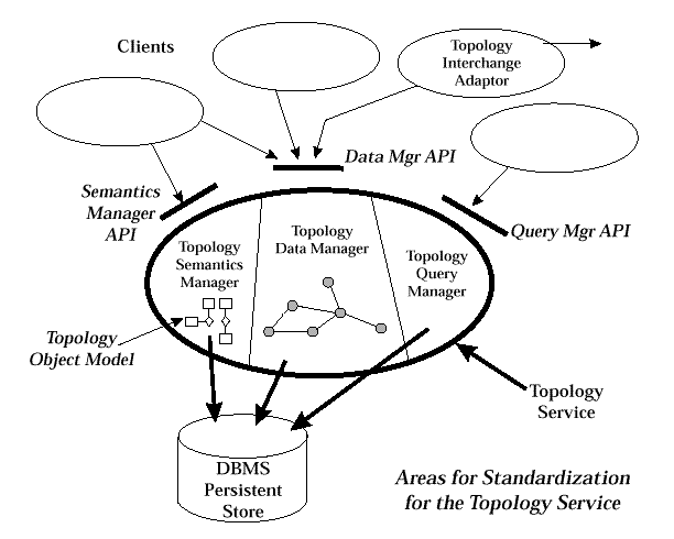
Figure: High-level Architcture View of Topology Service
Key Concepts
Topology
A topology is a set of valid associations between objects.
In the Topology Service the set of
valid associations in a topology is constrained by a set of
topology rules.
As an example in network management,
a TCP/IP network topology can be established which is governed by
rules dictating conditions such as:
-
all IP network addresses must be unique
-
a host can be connected to a network only if one of its network
interface cards has an IP
address which matches the address of the network.
As an example in system management,
topology rules can be established which define a
topology of users and distributed computing resources. Such a topology would consist of
associations that indicate how users map to various login accounts and what corresponding
access each has to particular system resources. The corresponding topology rules might
dictate how many users can simultaneously have access to a given type of resource, and under what conditions.
Entities and Aggregate Entities
The Need for Aggregates
Management interfaces to resources in a distributed network and system environment are
typically very complex. Although often viewed by their users as single components, managed
resources often consist of several, possibly tens of smaller, individually managed objects.
These smaller objects are often a mixture of logical and physical components which work
together to offer functional services to which applications can subscribe. Any or all of the
smaller components can change (due to upgrades, repairs, migration, physical moves, etc.)
Yet as these changes to underlying components take place, the combined resource itself
(usually) persists. Such a combined resource is what users and administrators generally know
by a common name and perceive
in terms of the services its combined, underlying components provide.
Consider the example of a file system. While the file system is typically viewed as a whole, it
actually consists of a logical component and a physical component. The logical component is
a hierarchical file system (hfs) which defines the structure of contained files and directories.
The physical component, is a hard disk device which has its media organized by the hfs.
Together they form the file system. Both are required, yet each can be managed individually.
For example:
-
by taking the appropriate steps, the hard disk can be
replaced with another, while still
retaining the file system as it is known to its users
-
asset management of the physical hard drive is handled without
any consideration given
to the hfs implemented over it
-
by logically mounting the hfs to another location in the computer
system's complete file
system structure, the file system has moved,
yet physically it has been unaffected.
Consider now the administrator's desire to export the file system to clients via NFS. To do so,
another logical component is needed: an
exported file system
which provides a remote
access point for mounting and which retains a list of clients who may have access to the
exported file system. There are several points worth noting in this example:
-
The
exported file system
component also represents the file system, along with the hfs and hard drive components - yet it has a very different lifecycle.
-
Not every file system gets mounted. Thus, only those being exported require the
additional
exported file system
component.
-
It is the
exported file system
which participates in an NFS topology which in turn identifies the
clients and servers forming the
distributed
file system. The other file system components,
such as the hfs and the disk drive,
neither have knowledge of NFS nor should they.
-
If this file system were exported instead via non-NFS protocols (such as those provided by
Netware), a variation of the NFS
exported file system
would be required to adequately manage the export.
-
If this file system were exported via both NFS and Netware, it would be appropriate and
correct to have an
exported file system
component for
each,
so that the facets of each
exporting environment can be managed individually and independently.
So, in this example, we see a single resource - a file system -
which is nevertheless based on multiple, underlying components. Some of
these components always exist
while others may
come and go more frequently, and yet all require some degree of individual
management.
This example illustrates a frequently-encountered situation:
-
Resources and services are often viewed as units because they operate as units, yet they are truly a
collection of cooperating components that must be individually managed. Furthermore, it is the
underlying components that characterize a resource's participation in various topologies.
This situation raises two issues for resource management:
-
How does one best maintain the perspective, identity, and longevity of a combined resource, while
allowing direct management access to its underlying components as individual entities?
-
How does one appropriately model a resource to allow it to participate in a variety of topologies, some of
which are physical, some of which are logical, some of which are seemingly in conflict with one another,
and some of which are not even conceived yet?
A solution to this problem would make sufficiently transparent
the key underlying components that intrinsically form a resource
as well as the topologies those components
participate in. Such a solution becomes highly useful in:
-
bridging the gaps between logical and physical worlds that interact together to form
resources
-
enabling traversals through and across separate topologies in which resource
components participate.
Both these situations characterize the nature of the networks and systems that make up
resource management. Consequently, applications providing
integrated
management of:
-
networks
-
systems
-
networks
and
systems
-
distributed applications which depend on both networks and systems
would all benefit fundamentally from such a solution.
The Topology Service provides a solution to this problem
through means of a special relationship, called aggregation1.
Internal
to Topology, individual managed objects, such as
the hfs, the hard disk, and the exported file system in the above example, are
represented
by
topological entities.
When topological entities are recognized to be part of a larger
resource (such as the file system in the example above) the
Topology Service can be told to join them into an
aggregate entity
(AE).
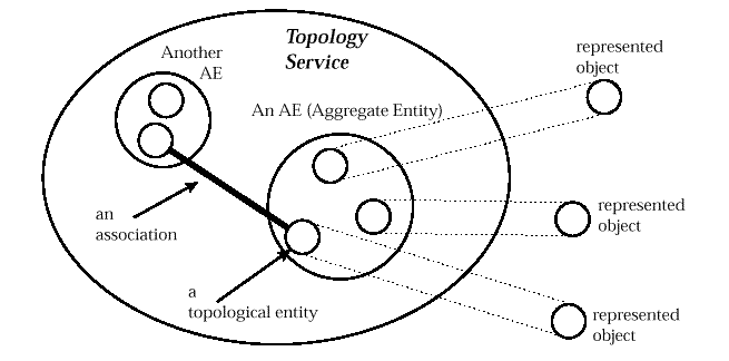
Figure: Topological Entities and Aggregate Entities
As a result, Topology provides aggregate views, as well as individual entity views, of the
components that participate in the topologies it stores2.
In the above file system example, aggregation means that access can be made to the file
system AE, whereby information pertaining to its topological
entities - its hard disk, its hfs, and any exported file systems - are
immediately available. From the AE, any of the
topological associations that topological entities participate in can be seen and traversed.
AEs and Topological Entities in the File System Example
illustrates the
concept using the File System example for UNIX systems.
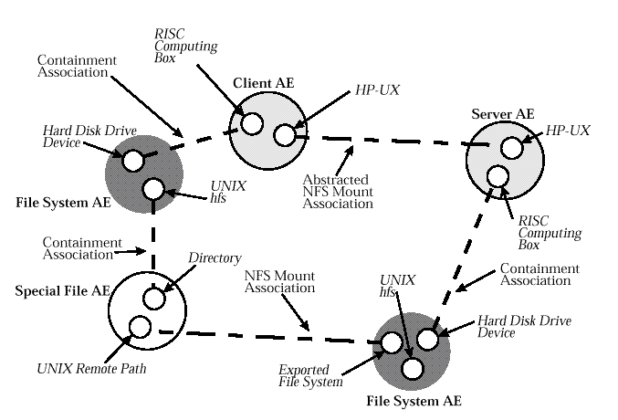
Figure: AEs and Topological Entities in the File System Example
This benefit of entity aggregation becomes evident when navigating through the topology
tree. AEs provide a degree of transparency whereby traversals from one topology to another
is readily accomplished via the topological entities that form an AE. In the above example,
the "Abstracted NFS Mount Association" between the Client and Server is in fact derived
from navigating through three types of topologies: physical equipment containment, logical
file system structure, and the NFS topology. The Topology Service query subsystem takes
advantage of the integration and transparency provided by AEs to make such a query easy to
specify and execute. Without the aggregation provided by AEs, such a query would be far
more cumbersome to develop.
Topology Rules
The Topology Service allows developers to
dynamically specify
topology rules
which must be met for every instantiated association.
As part of these rules, the
object-oriented concept of
type
is used
to distinguish different entities that make up an AE.
Every topological entity is assigned such a
topological type.
Based on these types, topology rules express the kinds of
associations allowed with various other topological types3.
Examples of topological types include NFS Server and NSF Client
for an NFS topology.
For an SDH topology, topological examples include Virtual
Circuit, Trail, Add-Drop Multiplexer and Synchronous
Digital Crossconnect.
Note that topological types are managed purely as a Topology Service concept.
Developers
can define new types and assign them to entities in whatever manner makes sense for their
applications and for the topologies being represented. In practice, however, topological
types will typically correspond directly to the
interfaces
exposed by the
objects
represented by topological entities.
The topological types assigned to entities are transitive to their AEs. Thus, an AE takes on all
the topological types of its entities.
Associations
are characterized by
roles
and by
cardinality.
Association
roles
dictate the
parts played by topological types on either end of an association. Association
cardinality
indicates the minimum and maximum number of these associations that can be established
with an entity of a given topological type. Associations in Topology are strictly binary in
nature, that is, each association links exactly two topological entities. (Relationships of
degree n are modelled by representing the relationships as Topological Entities themselves.)

Figure: Topology Object Model
Fusion Method of Object Modelling
The topology object model (see
Topology Object Model
)
is based on the
fusion
method of object modelling,
as explained in referenced document
OODFM.
Conventions in the Fusion method include the representations
shown in
Conventions in Fusion Object Modelling Method
.

Figure: Conventions in Fusion Object Modelling Method
Topology Queries
Topology allows a user to make arbitrary queries of topological data. A query always returns
a boolean value indicating whether or not a match was found and optionally the actual AEs that matched the query.
A query is expressed in the form of a
navigation path
which is used by Topology to navigate
through the topology graph in search for matching AEs. A navigation path includes one or more
AE-patterns
interconnected by
association-patterns.
association-pattern.
An
AE-pattern
is a string expression of AE selection criteria.
The
AE-pattern selection criteria
consists of an AE name or an expression of topological types.
An
association-pattern
interconnects
AE-patterns to designate the criteria for selecting
associations while navigating through the topology graph
from one AE to another. An
association-pattern uses an expression of role names as a basis for selecting associations.
Textual examples of queries which can be formulated include:
-
"get all the laser printers that are associated via serial cables with this computer"
(assuming that
laser printer,
computer
and
serial cable
are types of AEs whose valid associations conform to a
topology managed by the Topology Service)
-
"list all the programs that can be executed by the users who can execute Program A"
(assuming that a
Program A
is an existing topological entity
and that
person
and
can execute
are AEs whose valid associations
conform to a topology managed by the Topology Service).
Queries are expressed textually using a
Topology Query Language (TQL).
Queries can be parameterized so their
execution point in the topology graph can be determined at execution time.
Development Process
Service Development Process
Typical Topology Service Development Process
shows a typical process for developing a sub-product which
uses the Topology Service.
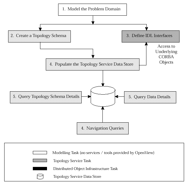
Figure: Typical Topology Service Development Process
Creating a Topology Schema
Typical Process for Creating a Topology Schema
shows a typical process for creating a topology schema
for a client which uses the Topology Service.

Figure: Typical Process for Creating a Topology Schema
Typical Process for Defining IDL Interfaces
Typical Process for Defining IDL Interfaces
shows a typical process for defining IDL interfaces for a client which uses the
Topology Service.
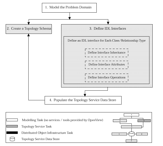
Figure: Typical Process for Defining IDL Interfaces
Populating the Topology Service Data Store
Typical Process for Populating Topology Service Data Store
shows a typical process for populating the Topology Service data store.
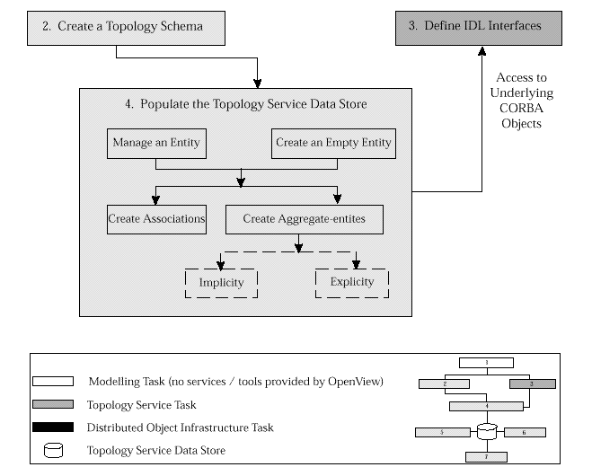
Figure: Typical Process for Populating Topology Service Data Store
Development Example
As an example for defining a topology to be managed by the Topology Service, consider an
extension to the File System example which incorporates PC NFS clients.
Topological Entities and Associations for PC NFS Example
shows an example subgraph of what such a set of topologies might look like within the
Topology Service. Note that the example assumes some extensions to the object model, which
includes new topological types (for example,
PC Box, DOS Disk hfs, DOS network drive, and a
Windows95 Operating System).
A corresponding object model on which the example
topologies are based is shown in
Portion of Object Model for Development Example
.
4
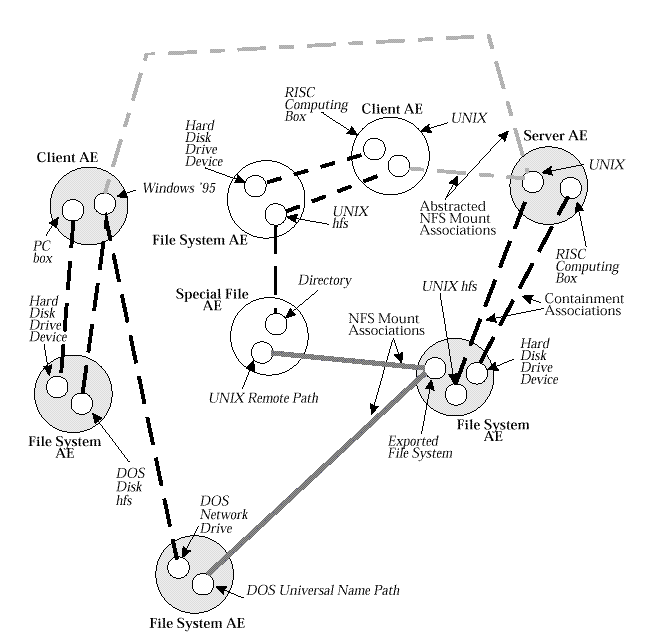
Figure: Topological Entities and Associations for PC NFS Example
In developing the example, we establish topology rules for
two topologies: NFS, and
OS-hierarchical file systems. The topological types these entail include:
-
OS subtypes:
-
logical volume and its subtypes:
-
UNIX hfs
-
DOS disk hfs
-
DOS network drive
-
file system path and its subtypes:
-
directory
-
special file subtypes:
-
remote path (UNIX)
-
universal name path (DOS)
-
exported file system
-
physical computing equipment
-
RISC computing box
-
PC box
-
physical peripheral devices
These are shown as shaded in
Portion of Object Model for Development Example
.
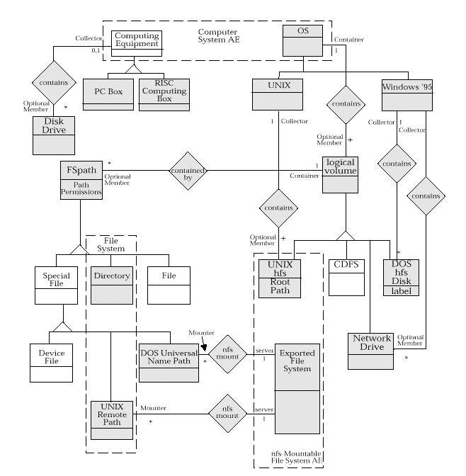
Figure: Portion of Object Model for Development Example
Once the object model is defined,
with association roles and cardinality labeled, the topology
rules can be written down. The rules are developed for each topological type to express the
kinds of associations that topological type can participate in.
Each topology rule specifies a role name, and a minimum and maximum number of
associations in which the entity can participate in that role,
along with the topological type of the
associated
entity.
Topology Rules
shows the topology rules used for this example for the eight types of
associations (denoted by the diamond-shaped boxes in
Portion of Object Model for Development Example
).
| Association
| Topological Type
| Topology Rules
|
|---|
| | | _
|
|---|
| | | Role
| Min
| Max
| Associated Entity's
|
|---|
| | | | | | Topological Type
|
|---|
| 1
| OS
| container
| 1
| infinite
| Logical Volume
|
| | Logical Volume
| optional member
| 1
| 1
| OS
|
| 2
| Windows '95 OS
| collector
| 0
| 26
| DOS disk hfs
|
| | DOS disk hfs
| optional member
| 1
| 1
| Windows '95 OS
|
| 3
| Windows '95 OS
| collector
| 0
| 26
| DOS network drive
|
| | DOS network drive
| optional member
| 1
| 1
| Windows '95 OS
|
| 4
| UNIX OS
| collector
| 1
| infinite
| UNIX hfs
|
| | UNIX hfs
| optional member
| 1
| 1
| UNIX OS
|
| 5
| Logical Volume
| container
| 0
| infinite
| FSpath
|
| | FSpath
| optional member
| 1
| 1
| Logical Volume
|
| 6
| UNIX remote path
| mounter
| 0
| 1
| Exported File System
|
| | Exported File System
| server
| 0
| infinite
| UNIX remote path
|
| 7
| DOS universal name path
| mounter
| 0
| 1
| Exported File System
|
| | Exported File System
| mounted
| 0
| infinite
| DOS universal name path
|
| 8
| Computing Equipment
| collector
| 0
| 32
| Disk Drive
|
| | Disk Drive
| optional member
| 0
| 1
| Computing Equipment
|
Table: Topology Rules
With the Topology Rules defined and made known to the Topology Service,
topological associations can be realized.
Sample Topology with Entities
shows a sample topology, whose associations are represented in
Valid Associations
.
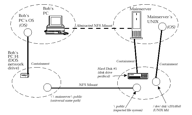
Figure: Sample Topology with Entities
With the specified constraints, the developer can create the associations
identified in
Valid Associations
.
| Entity
| Entity's Role
| Associated Entity's
| Associated Entity
|
|---|
| | | Role
|
|---|
| Windows '95 OS on Bob's PC
| Container
| Optional Member
| Drive H: on Bob's PC
|
| \\hpcndfs1\public universal name path on Bob's PC
| Mounter Server
| /public exported file system on hpcndfs1
|
| /dev/dsk/c201d0s0 on hpcndfs1
| Optional Member
| Collector
| HP-UX OS on hpcndfs1
|
| hard disk drive #5
| Optional Member
| Collector
| mainserver RISC Computing Box
|
Table: Valid Associations
Note that the
Abstracted NFS Mount
association between Bob's PC
and the main server
can be added as well (provided the topological rules are established first5).
This NFS Mount
association is an abstraction derived from underlying physical
and logical associations,
brought together through AE aggregation.
Adding Enforcers
If it is to be modelled correctly, there is at least one aspect of the NFS topology semantics that
the Topology rules cannot adequately describe and hence require an enforcer. Specifically, an
exported file system
entity has as attribute which indicates which remote clients are allowed
to establish a mount with it. This attribute consists of a list of hostnames with the designated
access each is allowed to have. The Topology rules cannot enforce this, but a registered
enforcer can. Note that this check by the enforcer requires information beyond the universal
name path and the exported file system, which are directly associated in the NFS Mount.
Validating the association for Bob's PC in the example requires following the association
from the DOS network drive to its containing OS (and its AE) to determine the hostname for
Bob's PC.
Queries
The Topology Service also provides a query language, as noted earlier, which allows
Topology clients to obtain topological information (such as the Abstracted NFS Mount
association described above and the path from which it is derived). The queries supported
provide transparency across AEs and thereby tie separate topologies together into seemingly
one, providing an powerful data integration paradigm.
Footnotes
- 1.
- The Aggregation relationship is considered "special" to Topology because it has certain characteristics that set it apart from the
administration of associations in general, as will become evident.
- 2.
- Note that objects are referenced, but not managed, by Topology.
Applications
manage objects, while
Topology
manages the topological characteristics pertaining to objects -
that is, the
Topological Entities,
the
Associations
between them, and the
Aggregate Entities
which provide a complete view of the entities being managed.
- 3.
- It is useful to note that the use of types allows
the expression of "topologies" to follow easily from the developer's
Object-Oriented Analyses (OOA) of their respective problem domains. See
Development Example
for an example of this.
- 4.
- This object model is also based on the
fusion
method of object modelling,
as explained in referenced document
OODFusion.
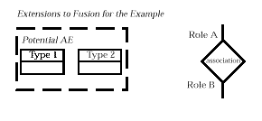
The following extensions to fusion are used in the figure in this
footnote, since AEs and
association roles are not fusion concepts.
- 5.
- These would consist of the following:
-
for the Computing Equipment Topological Type (a):
-
-
\{NFS client, 0, infinite, Computing Equipment\}
-
for the Computing Equipment Topological Type (b):
-
-
\{NSF Server, 0, infinite, Computing Equipment\}.
Why not acquire a nicely bound hard copy?
Click here to return to the publication details or order a copy
of this publication.


