
The Curing Process
A Case Study from the Tire Industry to Show the Use of Domain-Driven Design
A Case Study by:
Thierry Fraudet and Olivier Jauze
November 2021
Copyright © 2021, The Open Group
Licensed under the Apache License, Version 2.0 (the "License"); you may not use this file except in compliance with the License. You may obtain a copy of the License at: http://www.apache.org/licenses/LICENSE-2.0.
Unless required by applicable law or agreed to in writing, software distributed under the License is distributed on an “AS IS” BASIS, WITHOUT WARRANTIES OR CONDITIONS OF ANY KIND, either express or implied. See the License for the specific language governing permissions and limitations under the License.
Figures 4 and 5 are made available under the terms of the Attribution-ShareAlike 4.0 International (CC BY-SA 4.0) license: http://creativecommons.org/licenses/by-sa/4.0/.
The Open Group gratefully acknowledges Michelin and contributors, for the previous work on which this Case Study builds. See https://github.com/michelin/Continuous-Architecture-Toolkit. The Open Group gratefully acknowledges the Domain-Driven Design project for Figures 4 and 5 (see https://github.com/ddd-crew/welcome-to-ddd/).
Any publication of The Open Group may include technical inaccuracies or typographical errors. Changes may be periodically made to these publications; these changes will be incorporated in new editions of these publications. The Open Group may make improvements and/or changes in the products and/or the programs described in these publications at any time without notice.
Should any viewer of this document respond with information including feedback data, such as questions, comments, suggestions, or the like regarding the content of this document, such information shall be deemed to be non-confidential and The Open Group shall have no obligation of any kind with respect to such information and shall be free to reproduce, use, disclose, and distribute the information to others without limitation. Further, The Open Group shall be free to use any ideas, concepts, know-how, or techniques contained in such information for any purpose whatsoever including but not limited to developing, manufacturing, and marketing products incorporating such information.
If you did not obtain this copy through The Open Group, it may not be the latest version. For your convenience, the latest version of this publication may be downloaded at www.opengroup.org/library.
ArchiMate, DirecNet, Making Standards Work, Open O logo, Open O and Check Certification logo, Platform 3.0, The Open Group, TOGAF, UNIX, UNIXWARE, and the Open Brand X logo are registered trademarks and Boundaryless Information Flow, Build with Integrity Buy with Confidence, Commercial Aviation Reference Architecture, Dependability Through Assuredness, Digital Practitioner Body of Knowledge, DPBoK, EMMM, FACE, the FACE logo, FHIM Profile Builder, the FHIM logo, FPB, Future Airborne Capability Environment, IT4IT, the IT4IT logo, O-AA, O-DEF, O-HERA, O-PAS, Open Agile Architecture, Open FAIR, Open Footprint, Open Process Automation, Open Subsurface Data Universe, Open Trusted Technology Provider, OSDU, Sensor Integration Simplified, SOSA, and the SOSA logo are trademarks of The Open Group.
Miro is a registered trademark of RealtimeBoard, Inc.
All other brands, company, and product names are used for identification purposes only and may be trademarks that are the sole property of their respective owners.
The Curing Process
Document No.: Y211
Published by The Open Group, November 2021.
Updated November 2022 to remove proprietary information from some graphics.
Any comments relating to the material contained in this document may be submitted to:
The Open Group, Apex Plaza, Forbury Road, Reading, Berkshire, RG1 1AX, United Kingdom
or by email to:
Boundaryless Information Flow™
achieved through global interoperability
in a secure, reliable, and timely manner
Executive Summary
This Case Study is based on a real-world example to illustrate the use of domain-driven design and event storming in the context of Digital Transformation.
The Case Study concerns the tire production company Michelin, and in particular the curing process.
Although the concepts presented in this document address the typical concerns that correspond to the curing process and a tire production company, they could be applied to different situations.
This work supports the application of The Open Group Open Agile Architecture™ Standard.
Note: The content of some figures is intentionally obscured by the authors to remove proprietary information.
Introduction
Domain-driven design[1] is set of concepts and practices intended to align the structure and language of the software code with the business domain the code is supporting. It was popularized by Eric Evans (see References) and has gained a lot of traction in the last couple of years. One of the main difficulties when trying to adopt domain-driven design to model and design your solution is knowing exactly where to start.
We wrote this case study, inspired by a real use-case, to present an approach for applying domain-driven design to architects trying to design a product. This is not the only approach, but it may be a useful guideline.
Background and Context
In the tire industry, tires are produced by cooking or curing a raw, so-called green tire (a combination of rubber and metallic layers). This process takes place in plants in the curing shop where press lines, composed of press machines, are steered in parallel by an information system.
From a high-level standpoint, the curing process is quite simple. Before being able to cure a given tire dimension on one or some presses, we need to push the curing recipe to the press(es) and assemble and mount the tooling (mold and bladder set) inside a given press.
The first green tire is then consumed by the press which pushes information along the curing cycle. Once this cycle is finished, the final curing information is received, so we can control the quality of the curing, identify any non-conformities, and create the curing card (a birth certificate for a tire, if you will).
Then the next green tire is called by the press. Of course, the press keeps sending monitoring information of its own state so that any issues or downtime can be identified.
Applying Domain-Driven Design in this Context
Explore your Domain with an Event Storming
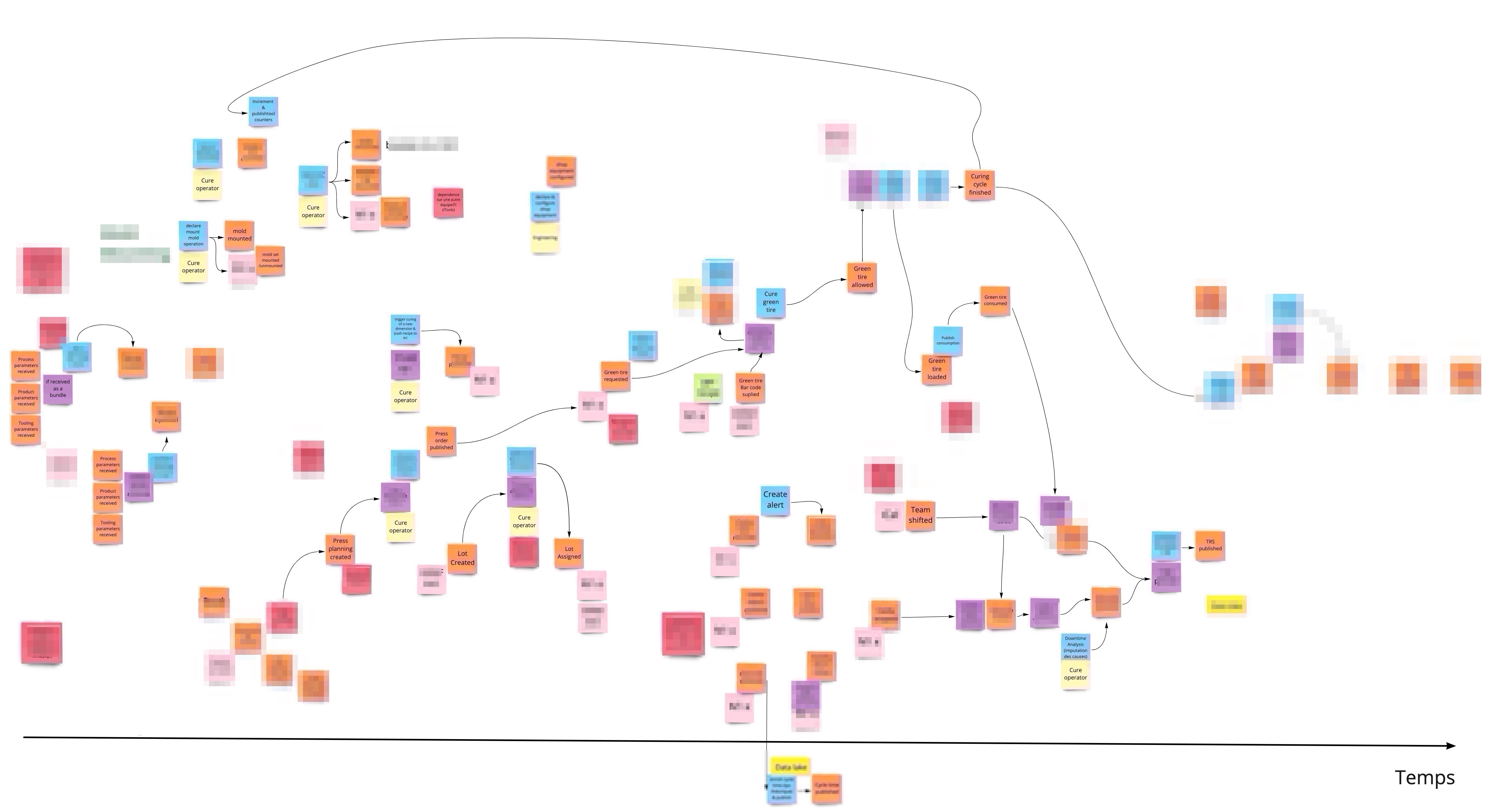
Before getting to the architecture work, you need to start modeling your business domain – in this case, the curing of tires. A good practice is to start with an event storming, as the objective of an event storming is to explore the domain by putting domain events on sticky notes along a timeline.
In other words, how would you describe your business domain with a set of business events? An event storming is a workshop in which business experts, architects, analysts, and developers collaborate to describe the business domains around the main business events. A domain event activates a policy that will issue a command/action from a system and this action will produce another event. Through a set of different colored sticky notes, a sequence of events is described. There are two important things to keep in mind when doing such a workshop:
- You must be very explicit and non-ambiguous in the terms you are using. Everyone in the group must be comfortable with the terms you are using. This set of terms is what we call the ubiquitous language.
- You are not designing your solution but discovering the business domain on which you are working. Do not go too deep into the technical details. That is not the point yet.
Figure 1 shows the event storming we did for our domain, using the Miro® tool. It represents the curing process, but in a much more detailed way.
Decompose your Domain into Bounded Contexts
Once the event storming has been completed, the results can be used to identify the different bounded contexts of your domain. These contexts simplify the architecture of your system by separating the concerns. They also help to create autonomy, as each of them can evolve at a different pace without impacting the others. Among other things, they enable technical partitioning, where each context can have a specific technical stack, and can scale differently. This technical partitioning can influence the organizational partitioning: we may assign autonomous teams on these contexts and promote parallel working.
There is no easy formula for identifying your contexts and decomposing your domain. Figure 2 suggests some criteria you can use. Some are business (different language, different value streams), others are linked to non-functional requirements (performance, scalability, etc.), and in some cases a different rate of change can also be used.
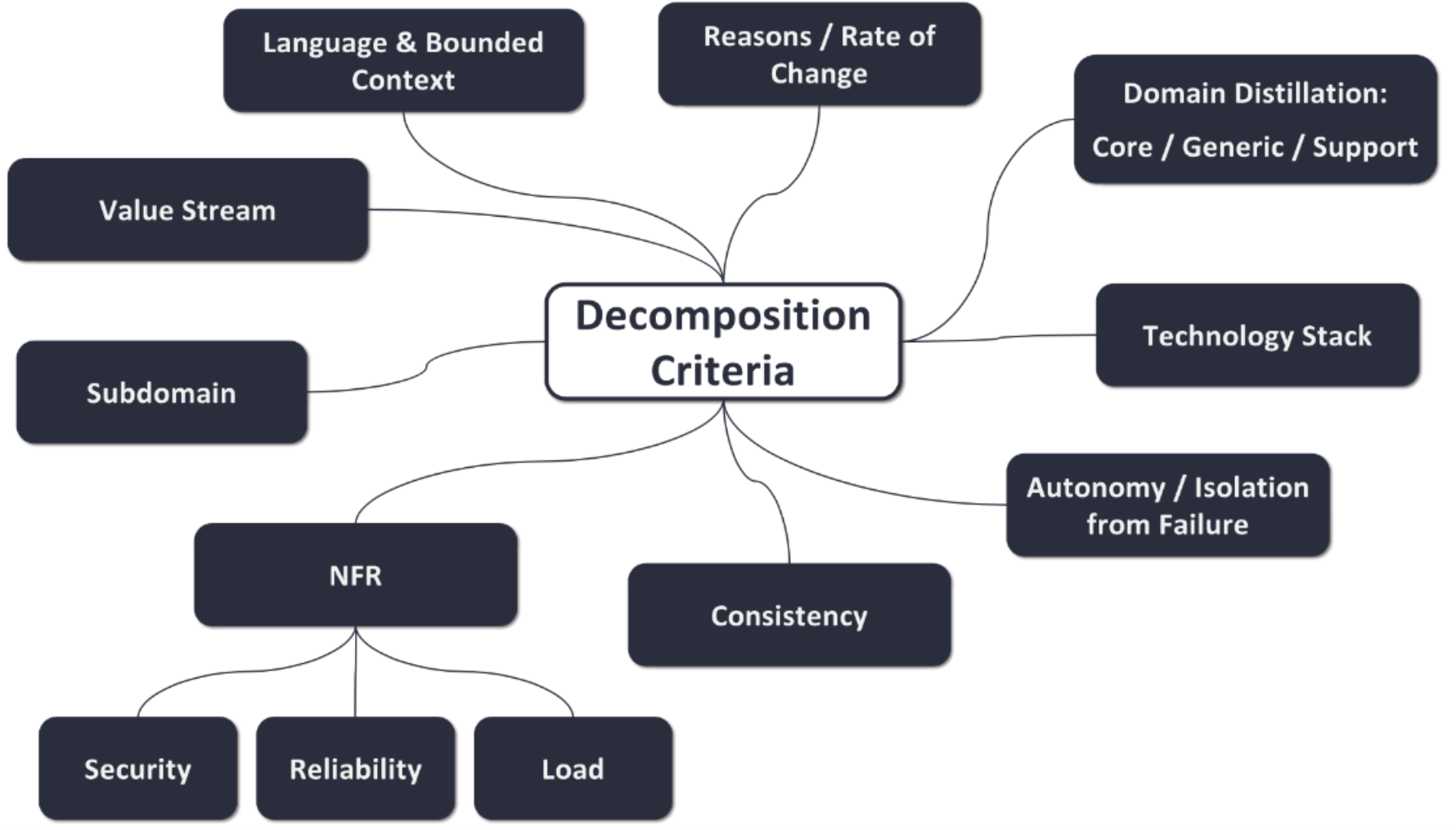
Figure 2: Context Decomposition
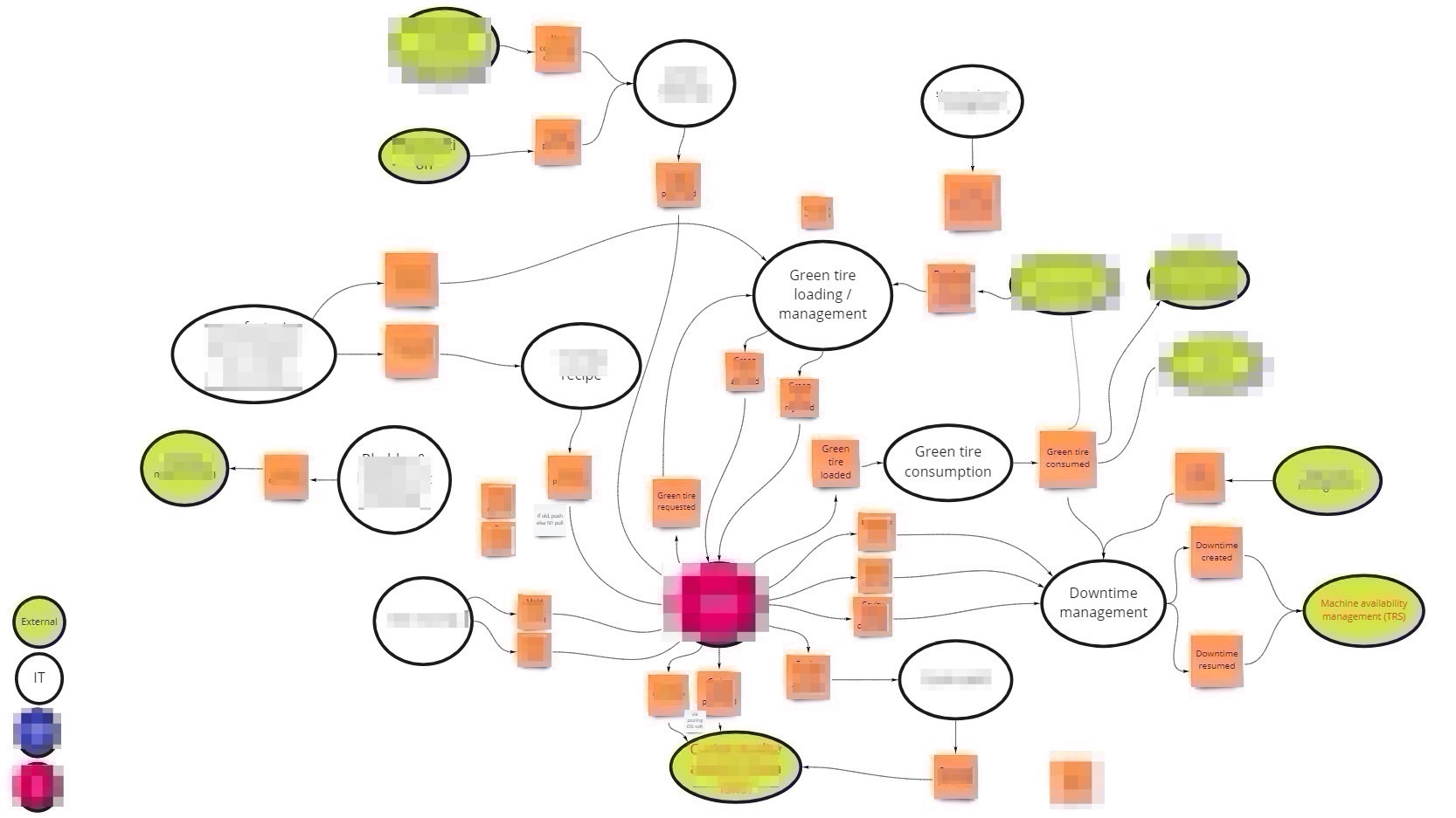
Using these criteria to identify our contexts, we arrived at three types of contexts:
• Supporting Contexts: providing referential data (bill of material, recipe, etc.), managing shop equipment, and tooling (molds and bladder sets)
• Core Contexts: loading green tires in the press, consuming green tires, creating the cure cards, managing downtimes
We found only one context for the press machine. It is a kind of monolith in a sense, but we had no choice. Indeed, given the way machine software is developed there was no way for us to decompose this big context into smaller pieces. It is a single unit of deployment.
• External Contexts: contexts that are outside of the business domain and with which we must communicate
Once identified, the next step is to highlight the business events generated by one context and consumed by others. We call them pivotal events. Figure 3 shows the result of this exercise.
Defining the Coupling Between Contexts with a Context Map
Even if the goal of a bounded context is to provide autonomy, there will still be some dependencies between them. The purpose of the context map is to give a holistic overview with regard to the coupling of bounded contexts, and ultimately between teams. The context map tool describes the contract between bounded contexts and teams with a collection of patterns. There are nine context map patterns and three different team relationships.
The Team Relationship
If we keep in mind that there could be one team behind each context (even if a team is in charge of several contexts in some cases), the relationship between teams can be classified according to three categories (see Figure 4):
• Free: no relationship
• Mutually-dependent: these contexts need to be delivered together to work successfully
• Upstream-downstream: the actions of an upstream context influence the downstream one, while the opposite may not be the case
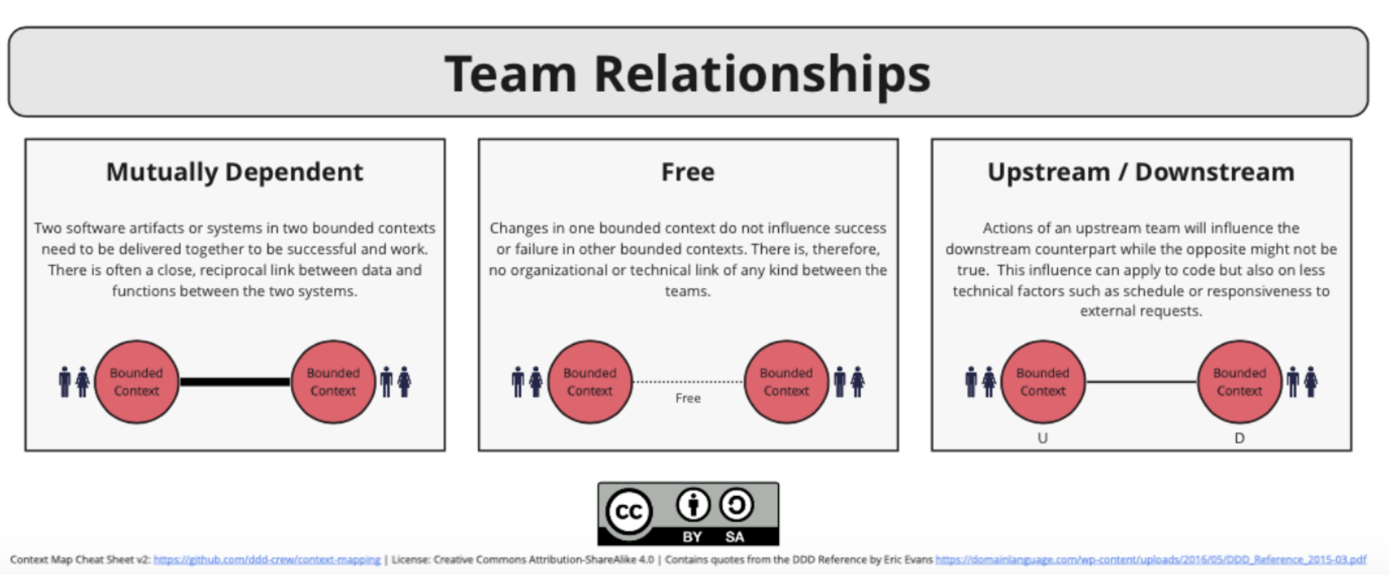
Figure 4: Team Relationships[2]
Integration Patterns
Once the relations between contexts have been clearly identified, you need to define which patterns best characterize these relationships. There are nine integration patterns, as depicted in Figure 5.
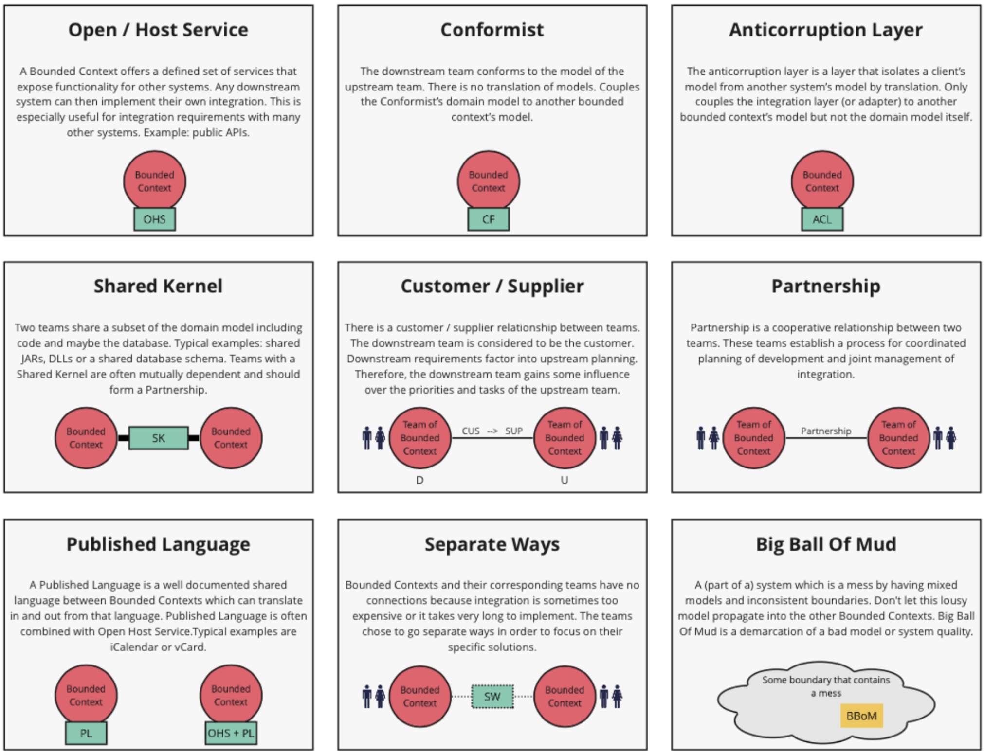
Figure 5: Integration Patterns[3]
This exercise is extremely useful in defining dependencies with other teams (i.e., between internal and external contexts), and how you want to shape those relationships.
In an upstream-downstream relationship, it is helpful to use this simple decision tree to define the pattern you should be using:
• If you are dealing with a language that is standardized across your domain or maybe beyond (up to your company), you should select the Published Language pattern
The Open/Host Service pattern is often used in combination, especially if you are implementing APIs. The format of the API is the Published Language pattern, and the Open/Host Service pattern indicates you are exposing this service to others. It is also valid for an event-driven approach as it can be considered as an asynchronous API.
• If the downstream context is considered as the customer, meaning their requirements are considered by the upstream context, then choose the Customer/Supplier pattern
• If the Anticorruption Layer pattern is preferred, the downstream context has consumed the event or API provided by the upstream context, implement a transformation layer to prevent the upstream context language invading (or corrupting) the downstream context
This means we do recommend avoiding, if possible, the Shared Kernel, Partnership, and Conformist patterns as they introduce strong dependencies between contexts. Of course, there could be cases where it makes sense, but it is important to question whether such dependencies are desired.
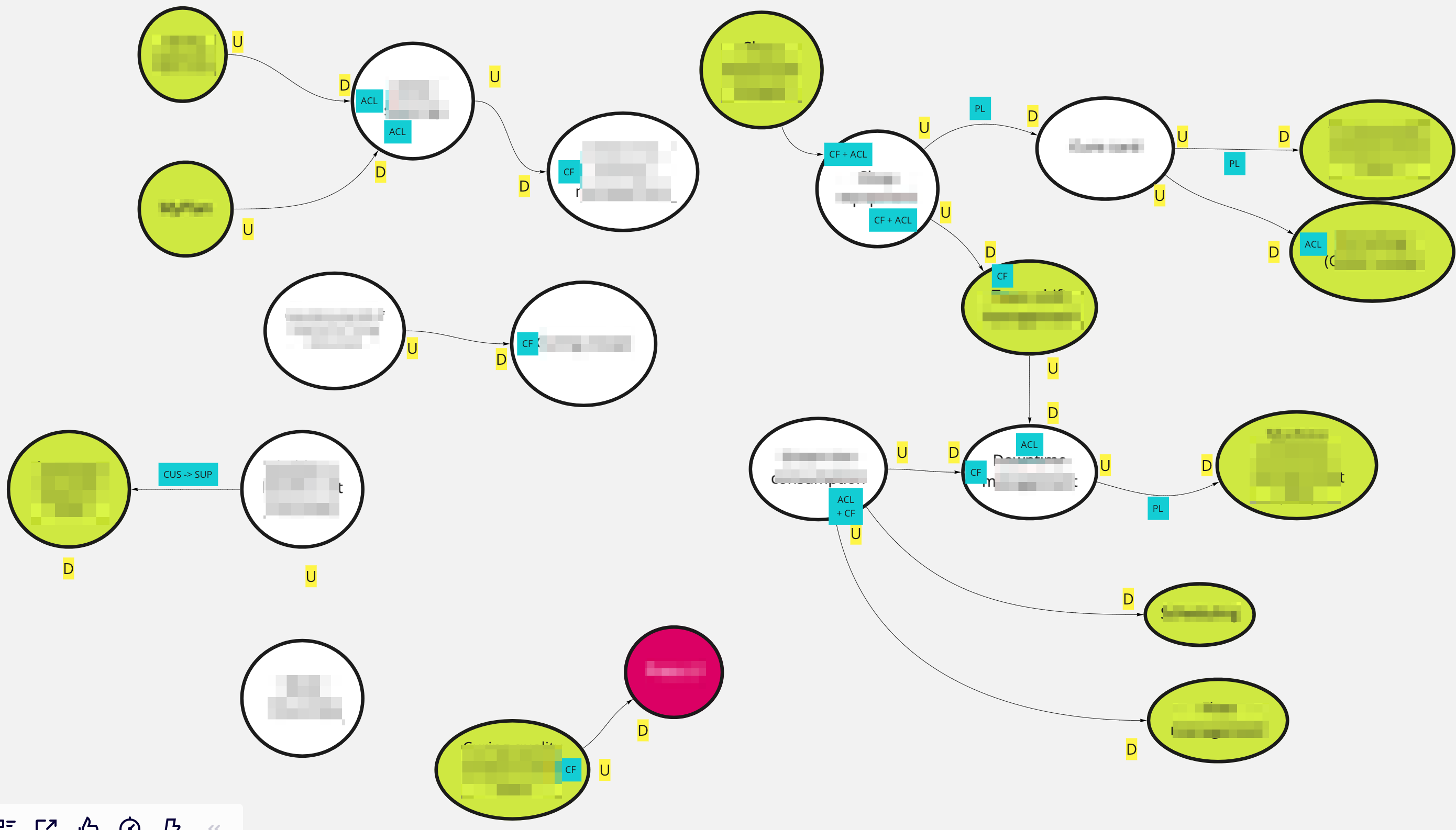
Figure 6 is the context map for our use-cases. Here are the main steps we took to arrive at such a map:
• “Shop equipment” and “Team shift management” were two contexts the company decided to standardize across the different plants; as such it made sense to conform to them as there was a strong willingness to standardize
• The “Machine availability management” consumes downtimes from “Downtime management”: the Published Language pattern seems to be a good fit as we wanted all shops (curing and others) to publish downtimes in the same manner
• The “cure card” is an event that is consumed by many other contexts (internal and external), so once again the Published Language pattern made sense
• We adopted the Anticorruption Layer pattern as much as possible to avoid corrupting our bounded contexts with language coming from other contexts
• We had one case where the Customer/Supplier pattern was chosen: inventories of bladders[4] are managed in accounting books leading to an integration with our Enterprise Resource Planning (ERP) system – the ERP was considered the customer and our bladder context had to consider the ERP requirements
Describing your Contexts in Detail
The next stop in your domain-driven design journey could be to describe the roles and responsibilities of your bounded contexts. Why? Before committing to architectural choices that are hard to change, we must consider essential trade-offs that can have a significant impact on your product development later. The bounded context canvas (see Figure 7) forces you to answer a series of questions about the design of a single bounded context that should be considered before committing to an architecture, team structure, or writing the code. How can you characterize the behavior of this context? Does it receive high volumes of data and crunch them into insights – an analysis context? Or does it enforce a workflow – an execution context? Identifying the different roles a context plays can help to avoid coupling responsibilities.
The canvas we used is a mix of visual representation and written text.
• The left part is used to describe the inbound communication initiated by other collaborators:
— “Messages” are the information that one collaborator sends to another
There are three types of conversation that can occur between bounded contexts: a request to do something (a command), a request for some information (a query), or a notification that something has happened (an event).
— “Collaborators” are other systems or sub-systems that send messages to this context
They can be other bounded contexts, frontends (web or mobile), or something else.
• The right part is then dedicated to outbound communications initiated by this context to interact with other collaborators
The same message types and notations apply as for inbound communication.
• Located in the middle is:
— Ubiquitous Language: what are the key domain terms that exist within this context, and what do they mean?
— Business Decisions: what are the key business rules and policies within this context?
Figure 7 shows the “curing recipe” bounded context description.
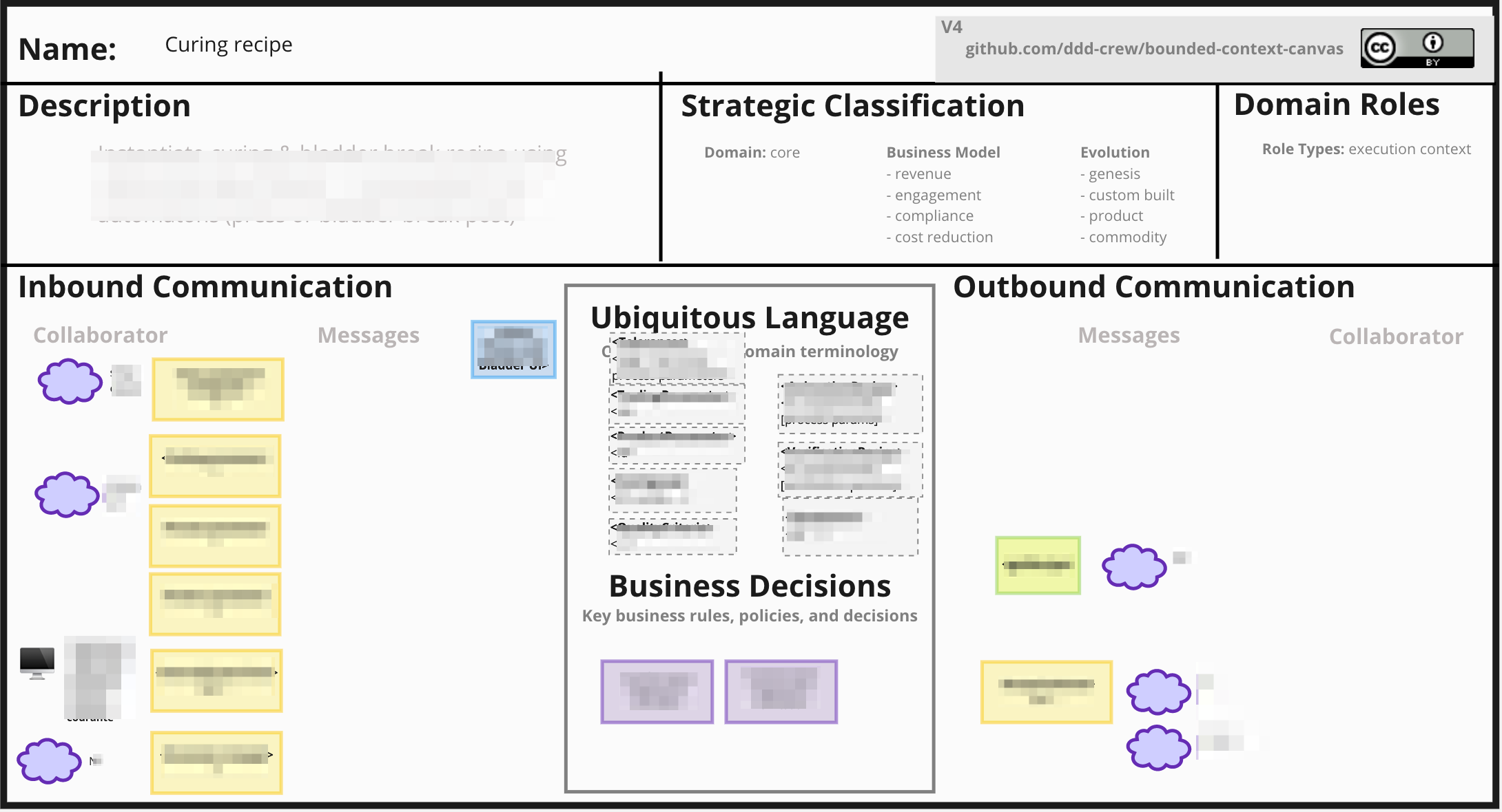
Figure 7: Bounded Context Canvas
Describe the End-to-End Dynamic
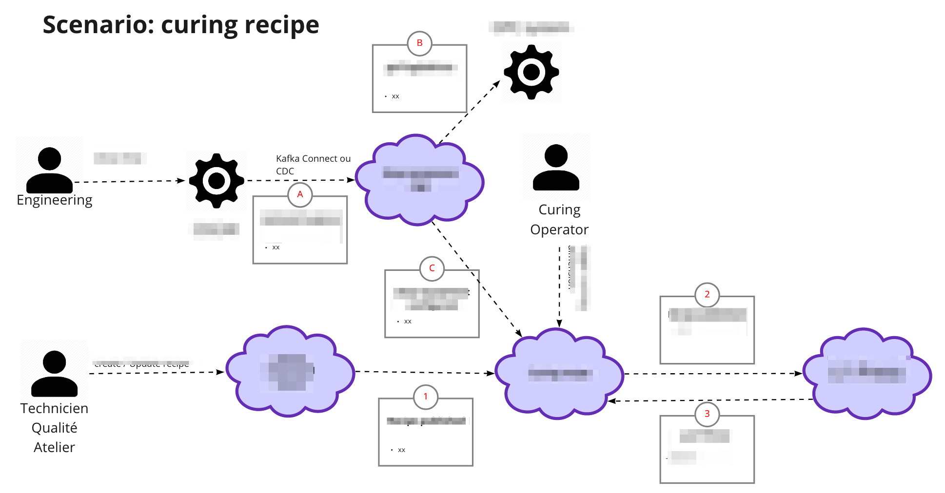
The bounded context canvas is a great tool to detail each of your contexts and to consider modularity. But it has one main drawback: the loss of the end-to-end view and the link with end-user needs. That is why we propose you complete the journey using the scenario tool. We usually start from an end-user journey and describe the sequence of tasks and events that this scenario will trigger across several bounded contexts. This last step is also an opportunity to check the coherence of the system.
Figure 8 shows the result of this practice on the curing recipe journey.
Additional Reflections
Once more, we would like to reiterate that this approach is just one way of applying domain-driven design; there could be other ways depending on your context. We strongly encourage you to adapt the approach if what we have proposed does not fit your context or constraints.
It is also interesting to reflect on the approach itself. Domain-driven design can be applied to the design of a product with a set of bounded contexts within the boundaries of your product. That is what we describe in this document. But it can also be used at a higher level for a large business domain, in which case the approach would be slightly adapted. Most of what we describe will be quite similar, but the level of granularity would be different. When you operate at a product level, the core context represents the different micro/macro services that compose it. But when you describe an entire business domain, these bounded contexts may represent products that could be described using domain-driven design.
References
(Please note that the links below are good at the time of writing but cannot be guaranteed for the future.)
• Domain-Driven Design: Tackling Complexity in the Heart of Software, by Eric Evans, August 2003, published by Addison-Wesley Professional
• The Open Agile Architecture™ Standard, also known as the O-AA™ Standard, a standard of The Open Group (C208), September 2020, published by The Open Group; refer to: www.opengroup.org/library/c208
About the Authors
Thierry Fraudet, Michelin
Thierry has been involved in the IT Industry since 1992 in a wide variety of contexts and companies (from start-ups to large international companies), which has enabled him to develop significant experience and expertise in Information Systems Architecture as well as Software Engineering, from large-scale distributed information systems to embedded software.
Currently working as an Enterprise Architect for the IT department at Michelin, his main focus is to develop the long-term IT technologies vision, articulate transformation roadmaps, and deploy IT capabilities to support business strategy and innovative thinking. Prior to that, Thierry was leading the Lean & Agile Transformation. He has been named as a Michelin Fellow for his significant contributions to the transformation of his company. Since 2020, he has been a member of the Board of Directors of the Club Urba-EA, a non-profit professional association that aims to develop Enterprise Architecture practices in French companies.
Olivier Jauze, Michelin
Olivier is an IT Distinguished Engineer at Michelin with almost 20 years of experience in Software Engineering and Architecture. Passionate in finding solutions to users’ problems with technology, Olivier coaches teams in their journey to deliver incredible products and, for a couple of years now, platforms too. Involved in many initiatives around Michelin core business, Olivier is also working in the service & solution and consumer experience areas. Recognized as a disrupter, he is continuously pushing organizations to adopt new business models and new ways of working. Recently he worked on an open source project to help software architects dealing with today’s continuous nature of software delivery.
About The Open Group
The Open Group is a global consortium that enables the achievement of business objectives through technology standards. Our diverse membership of more than 800 organizations includes customers, systems and solutions suppliers, tools vendors, integrators, academics, and consultants across multiple industries.
The mission of The Open Group is to drive the creation of Boundaryless Information Flow™ achieved by:
• Working with customers to capture, understand, and address current and emerging requirements, establish policies, and share best practices
• Working with suppliers, consortia, and standards bodies to develop consensus and facilitate interoperability, to evolve and integrate specifications and open source technologies
• Offering a comprehensive set of services to enhance the operational efficiency of consortia
• Developing and operating the industry’s premier certification service and encouraging procurement of certified products
Further information on The Open Group is available at www.opengroup.org.
[1] For a definition, refer to: https://en.wikipedia.org/wiki/Domain-driven_design.
[2] Courtesy of http://github.com/ddd-crew/bounded-context-canvas.
[3] Courtesy of http://github.com/ddd-crew/bounded-context-canvas.
[4] A curing bladder is a flexible membrane that forms the inside surface of a tire during the tire curing/vulcanizing process.
 return to top of page