11. IT4IT Definitions and Metamodel
This section formally defines all the concepts of the IT4IT Standard, which includes the IT4IT Metamodel.
The IT4IT Standard uses the ArchiMate modeling language, and thus the IT4IT Metamodel is defined as an IT4IT solution pattern in the ArchiMate language. This consists of the IT4IT Reference Architecture as a model specified in the ArchiMate language, which can be exchanged using the ArchiMate® Model Exchange File Format for the ArchiMate Modeling Language, Version 3.1 [C19C].
The IT4IT Standard is complemented with a simplified notation that makes it easier to communicate the high-level concepts of the IT4IT Standard to people not familiar with the ArchiMate language. Note that the simplified notation has a direct translation into the ArchiMate representation, and thus is as formal as the ArchiMate representation.
Most of the terminology used in the architecture is based on or derived from existing industry standard taxonomies. The architecture does introduce some new terms but this is only done when no other existing term could be utilized to express the intended meaning of the concept.
For the purposes of this document, the Merriam-Webster’s Collegiate Dictionary should be referenced for terms not defined in this section.
Note that the following definitions are ordered to reflect a hierarchy of refinement level as introduced in Section 11.2.
Refer to Appendix C for an alphabetic list of terms and concepts used in this document.
11.1. IT4IT Metamodel
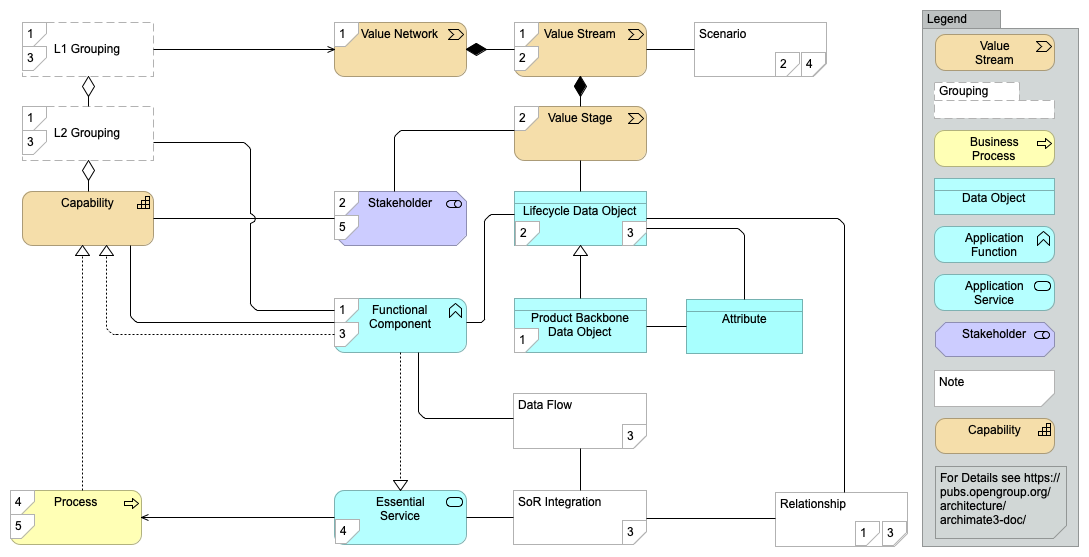
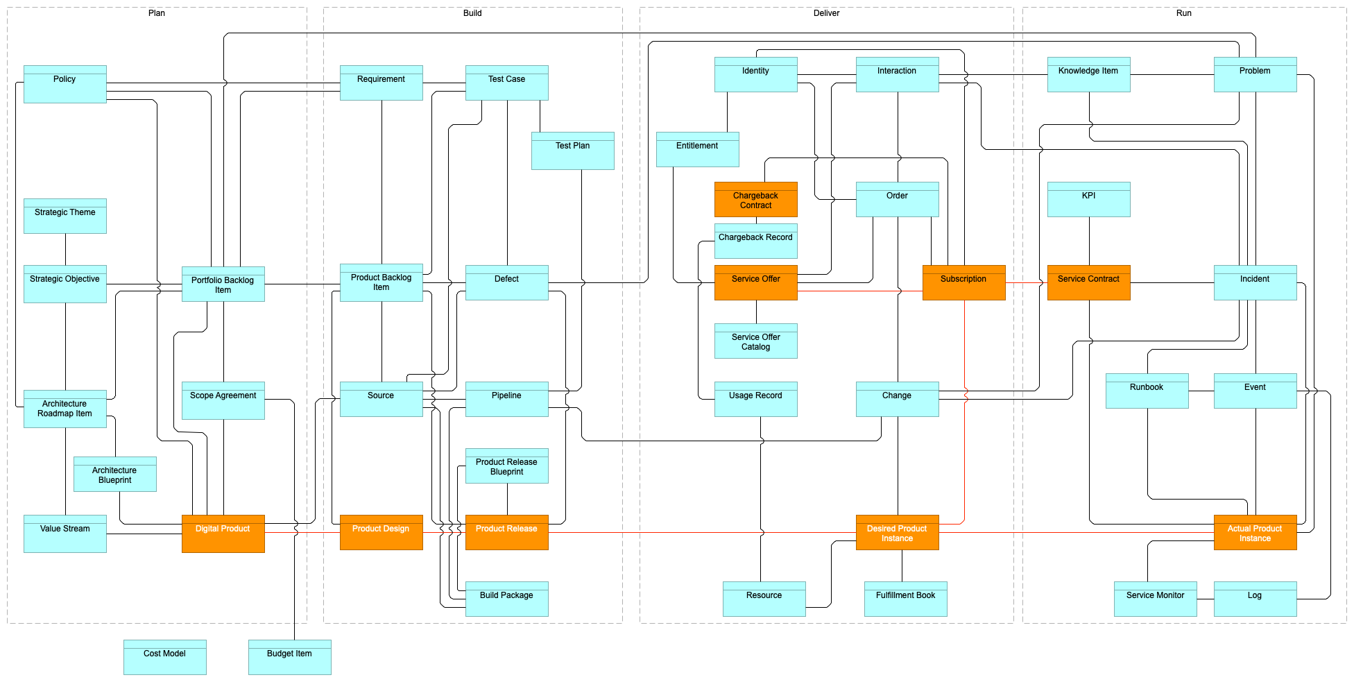
The IT4IT Standard introduces ten normative concepts as well as a number of complementary non-normative concepts. Their names and relations are pictured in Figure 75.
The number associated with each concept indicates at which abstraction level of the IT4IT Standard the concept is introduced. Some concepts are introduced at a high abstraction level but only formally defined further down; this is indicated by one or two numbers in the metamodel objects; see Section 11.2 for details.
11.2. IT4IT Abstractions
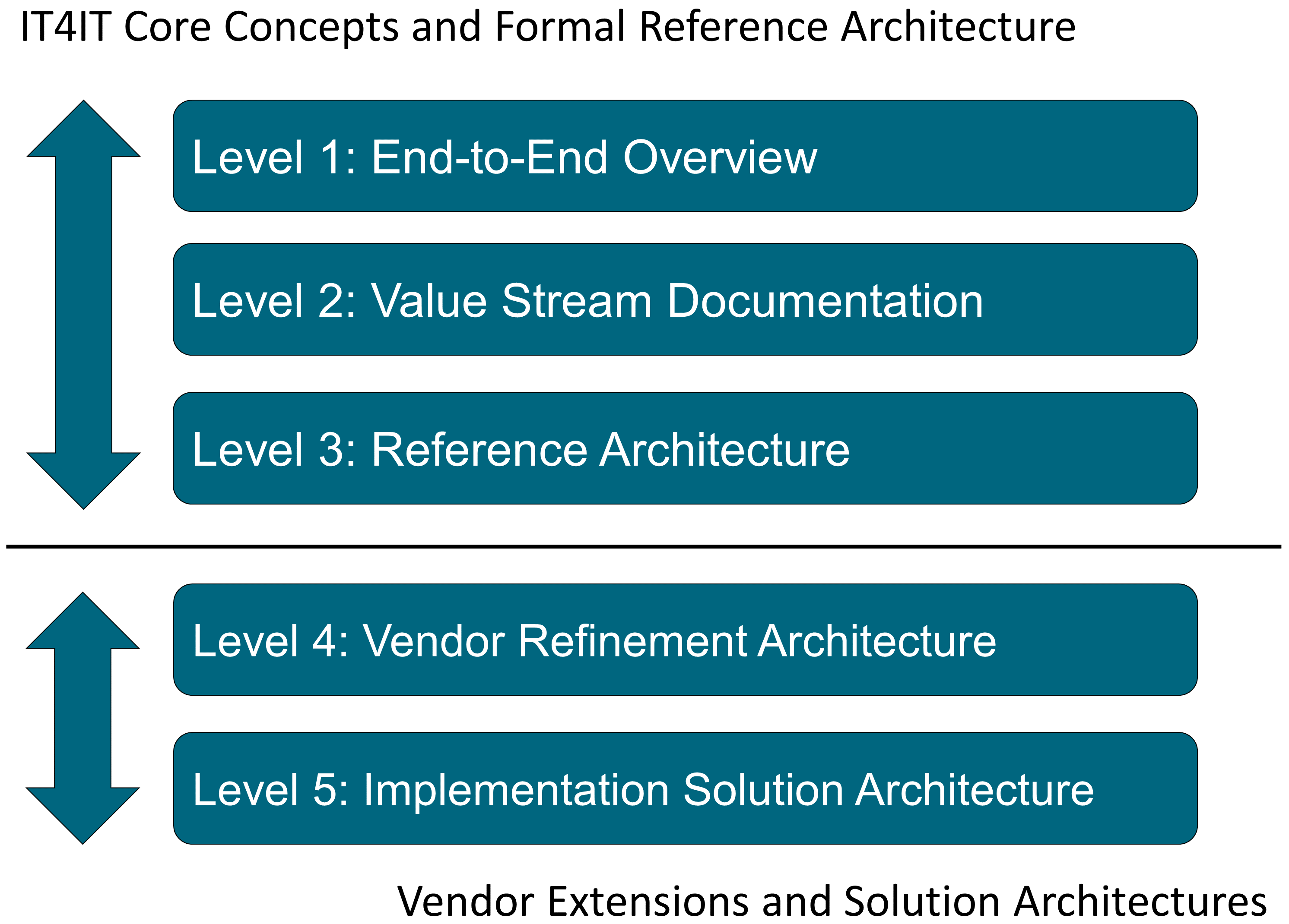
The IT4IT Reference Architecture is communicated using multiple levels of abstraction, which is inspired by a similar approach employed by the eTOM® frameworks from the TM Forum. Each abstraction level expands on the previous level to expose more details and prescriptive guidance. The upper levels are vendor and implementation-agnostic and provide generic views that are suitable for strategy and planning purposes as well as for creating roadmaps for implementing the IT4IT Reference Architecture. The lower levels provide specific details, ultimately arriving at implementation level or vendor-owned/controlled information. Content at these levels is suitable for developing implementation plans and for facilitating Product Design. The IT4IT Reference Architecture introduces five abstraction levels and standardizes the first three, as shown in Figure 76.
11.3. Level 1
Level 1 introduces the core concepts that make up the IT4IT Reference Architecture. These include:
-
The seven IT4IT Value Streams
-
The four high-level functional groups (plus the Supporting Functions) needed to manage the world of Digital
-
The notion of a Digital Product
-
The IT4IT concept of key data objects that control the lifecycle of Digital Products
-
The underpinning functional components that control the key data objects
This is documented in Chapter 3.
Following from this introduction, the concept of a Digital Product is defined in detail. Level 1 also introduces the concepts of the Product and Service Offer Backbone. This is documented in Chapter 4.
11.4. Level 2
At this level, the seven essential IT4IT Value Streams are defined as part of the normative standard. This is documented in Chapter 5.
This chapter also introduces the concepts of:
-
Value stream stages, as a refinement of value streams
-
Stakeholders
11.5. Level 3
At this level, the IT4IT functional components and data flow across them, the IT4IT data objects and their relations are defined as part of the normative standard.
This is structured into five chapters, one for each high-level functional group:
11.6. Formal Reference Architecture Model
Levels 2 and 3 of the IT4IT Standard constitute a formal reference architecture. In addition to being documented in the chapters referenced above, it is maintained as an ArchiMate® XML model in the ArchiMate model exchange file format.
The metamodel and associated definition of IT4IT terms are documented in Chapter 11.
The IT4IT model is complemented with some informative rationale as to reasoning and background information on the standard in Appendix B.
11.7. Concepts at Level 1: End-to-End Overview
Abstraction Level 1 is considered the “overview level”. It provides a holistic model of the IT4IT Reference Architecture, introducing the core terms and concepts that underpin the architecture. It depicts, at a high level, the foundational controls an IT organization needs in place to standardize, automate, and generally manage the IT4IT Value Chain.
At this level, six core concepts are introduced that are central to the IT4IT Reference Architecture body of work:
-
Value Network
-
IT4IT Value Streams
-
Management capabilities
-
Functional components
-
Data objects
-
Digital Product Backbone data objects
-
Service Offer Backbone data objects
-
-
Data relationships
11.7.1. Value Network
A Value Network is a construct that defines the relationships across the value-creating functions that deliver value.
Within the IT4IT framework it is used to describe the model of the digital business function. It includes primary activities such as planning, production, consumption, fulfillment, and support. It also includes supporting activities such as Finance, HR, Governance, and Supplier Management.
|
Note
|
The Value Network concept is an evolution of the Value Chain concept from Michael Porter’s book Competitive Advantage: Creating and Sustaining Superior Performance [Porter 1998]. |
The Value Network concept breaks with the waterfall-oriented aspect of the original Value Chain construct and makes each value-creating activity both consuming and value-producing to potentially many other activities.
11.7.2. Value Stream
A value stream describes the key value-creating activities for discrete areas within the Value Network where some unit of net value is created or added to the Digital Product as it progresses through its lifecycle. The IT4IT Reference Architecture defines seven essential value streams for digital management. These are referred to as the IT4IT Value Streams; see Figure 5.
Notation and Naming
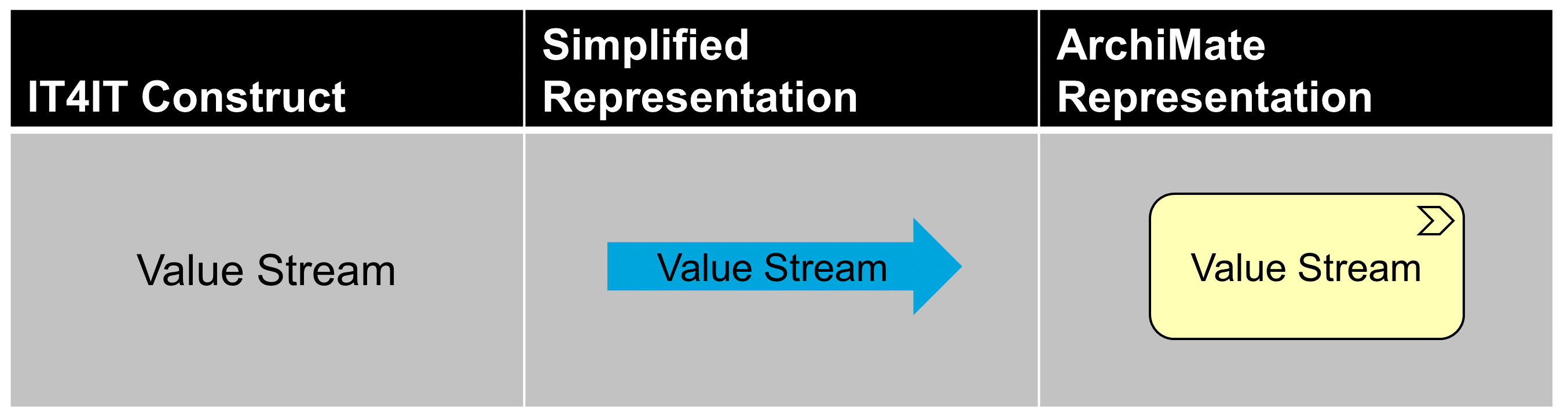
The IT4IT Standard has both a simplified notation and a notation aligned with the ArchiMate language, as pictured in Figure 77.
As a general rule, the IT4IT Value Streams are named using:
-
A verb that describes the essence of what the value stream is doing
Note that occasionally the verb can be used in connection with the essential (backbone) data object that the value stream works on. This is only in the description, and not the normative name. Also note that this document breaks with the tradition of using a x2y notation like “Detect to Correct”. This brings it more in line with how similar value streams are named in some Agile frameworks. Finally note that the value streams are not prepended with the word “continuous”, which is often found in Agile text books. The prepending of "continuous" is considered a maturity construct and should not be part of the name.
11.7.3. Functional Groups
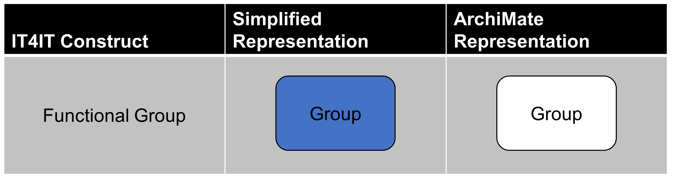
The IT4IT Reference Architecture uses the ArchiMate grouping construct as a way of grouping the functional components and data objects together to provide context for the functionality that organizations must deliver.
This can be used as a basis for capability planning in an organization but the standard does not prescribe what capabilities a Digital Organizations should build.
The normative IT4IT Standard defines a grouping at two levels:
-
Level 1: five high level groups of functionalities
-
Level 2: further decomposition into 14 groups
At Level 1, the IT4IT Standard defines the following functional groups:
-
Plan
-
Build
-
Deliver
-
Run
As well as the Support functions that are referenced but are not normative definitions in the IT4IT Standard.
Each one of these is then further decomposed at Level 2 to provide more structure to the reference architecture.
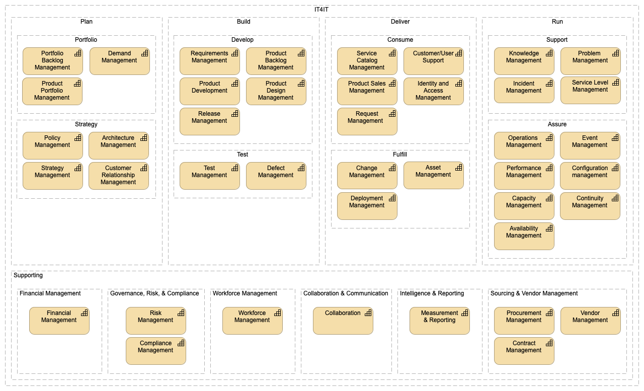
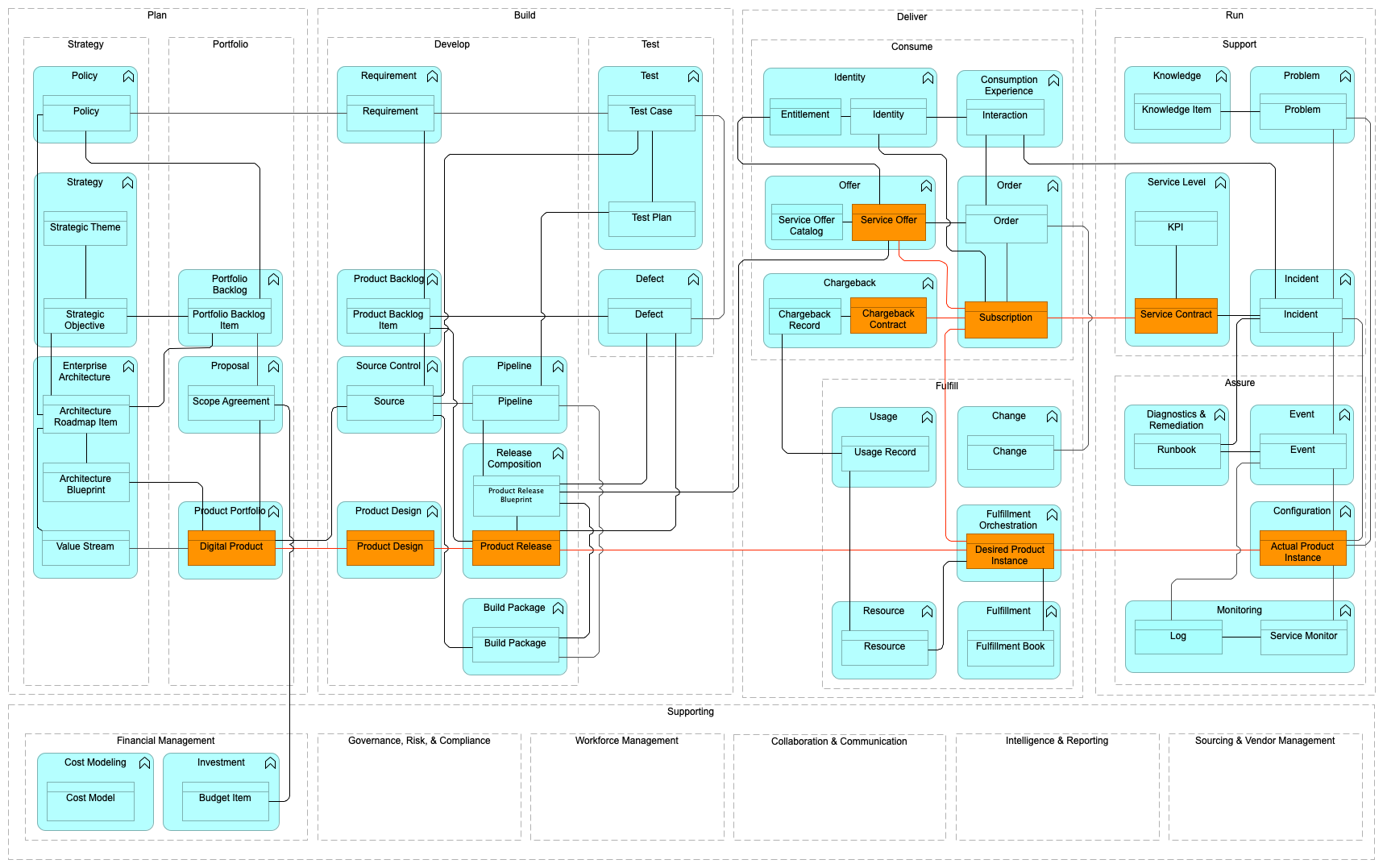
Note that the groupings are simply a way of grouping related functional components together to be able to talk about functionality in a more abstract way, such as Support functions, Assure functions, or simply Run functions. When the IT4IT Reference Architecture is used to implement Digital Management in a real organization it is necessary to also do capability mapping, as it remains an important activity for organizations. Detailed capabilities that would include process and people aspects are not included as part of the normative documentation. Instead, other documents (guidance documents) will provide this level of detail. The objective of the IT4IT Reference Architecture is to convey, in a prescriptive fashion, the key data objects, relationships, and components that are foundational for all IT organizations. Figure 78 gives an example of a possible decomposition of the IT4IT normative Level 1 and Level 2 groups into detailed capabilities.
There is also Supporting Functionality within the Value Network model, such as Supplier & Vendor Management, Workforce Management, and Financial Management. As with detailed capabilities, these do not normatively define the Supporting Functions, but do define some of the essential data objects and functional components that are expected from the Supporting Functions in order for the primary functionality and value streams to work.
Notation and Naming
The IT4IT Standard uses the ArchiMate grouping types and a containment notation to indicate decomposition and to illustrate which functional components support a given functional group.
|
Note
|
Figure 78 illustrates a number of capabilities. This is for illustration, and not normative. The IT4IT Standard only normatively defines a general grouping of functionalities and is not a formal capability model. |
As a general rule, the IT4IT Functional Groups are named using:
-
A verb that describes the essence of what the group of functions is performing
11.7.4. Functional Component
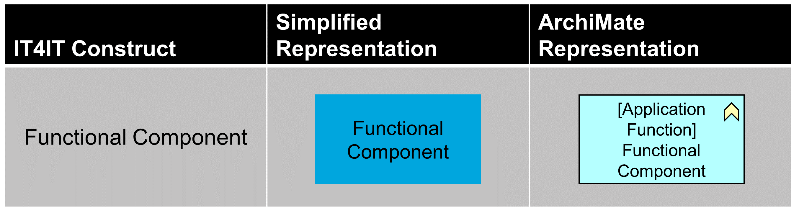
A functional component is the smallest unit of technology that can stand on its own and be useful as a whole to a digital practitioner (or IT organization). It must have defined input(s) and output(s) that are data objects and must have an impact on a key data object that it controls. Typically, a functional component controls and/or manages a single key data object, but this is not dictated by the architecture; it can control several, especially if they are intrinsically connected.
Examples of functional components include Event, Product Backlog, Defect, etc. The IT4IT Reference Architecture contains only those functional components that have an impact on key data objects. There will be other technology components and management systems that are used by IT organizations in the normal course of business, but those are not considered to be part of the prescriptive IT4IT Reference Architecture. Examples of these types of components could include Corporate Finance systems, HR applications, and Contract Management systems. These will be supplied by the Supporting Capabilities. These are not normative but in some cases the Reference Architecture will make reference to those.
Notation and Naming
The IT4IT Reference Architecture uses both a simplified and an ArchiMate notation style. At Level 1, the informal notation renders primary functional components as blue rectangles (see Figure 80). Secondary functional components are rendered as gray rectangles. Functional components are represented formally in the ArchiMate language using the “Application Function” type.
As a general rule, the IT4IT Functional Components are named using:
-
A noun or a noun with a qualifier that describes the essence of what the functional component is managing
Occasionally the name is appended with the word “component” as a shorthand for “functional component”
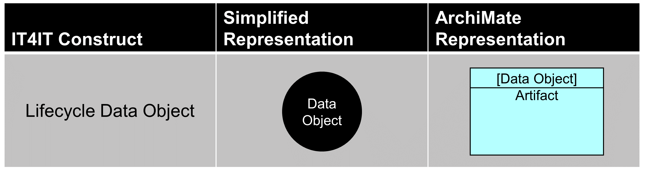
11.7.5. Lifecycle Data Object
A Lifecycle Data Object represents data (records, information, and so on) that annotate or model an aspect of a Digital Product being planned, developed, offered, or consumed. Data objects can take a digital or physical form and can be comprised of structured, semi-structured, or unstructured data. Our definition of Lifecycle Data Object is aligned contextually with the Object Management Group® (OMG®) definition of artifact. In UML, the OMG defines artifact as:
“… the specification of a physical piece of information that is used or produced by a software development process, or by deployment and operation of a system. Examples of artifacts include model files, source files, scripts, and binary executable files, a table in a database system, a development deliverable, or a word processing document, a mail message.” [UML]
Examples of data objects include incident records, training videos, requirements documents, etc. These types of data objects contribute in some way to define and control a Digital Product over the course of its lifecycle. There are also “special” data objects that represent an abstraction or view of a specific product; for example, a system diagram, release package, or a binary executable file; this provides a “view” of a product to various personas at different stages of the product lifecycle. These special data objects and their relationships form a “backbone” that binds together all of the information needed to offer and manage a Digital Product, thus they are referred to as Digital Product Backbone data objects.
The central focus of the IT4IT Forum has been to identify the data objects that play a “key” role in the service lifecycle. In other words, the reference architecture focuses exclusively on the data objects that are mandatory for ensuring end-to-end traceability of the product lifecycle operationally and/or financially. There are other data objects used across the digital landscape to facilitate various needs or activities (e.g., company-specific processes), but these are considered to be secondary or auxiliary and outside the prescriptive control of the IT4IT Reference Architecture.
Notation and Naming
The IT4IT Reference Architecture utilizes both a simplified and an ArchiMate notation for data objects so that the work can be easily understood by both architects and non-architects. In the Level 1 model, a simplified notation that depicts data objects as circles is used. Color is used to specify whether a data object is key data object (black) or a backbone data object (orange). Data objects are modeled formally in the ArchiMate language using the “Data Object” type, as shown in Figure 81.
Text is also important in communicating the concepts represented in the model. According to dual-coding theory, using text and graphics together to convey information is more effective than using either on their own. Further, the IT4IT Reference Architecture attempts to avoid using text that creates collisions between architectural layers (e.g., business function, data, and implementation layers). Level 1 introduces naming conventions for data objects that are rooted in the well-known IT frameworks and standards.
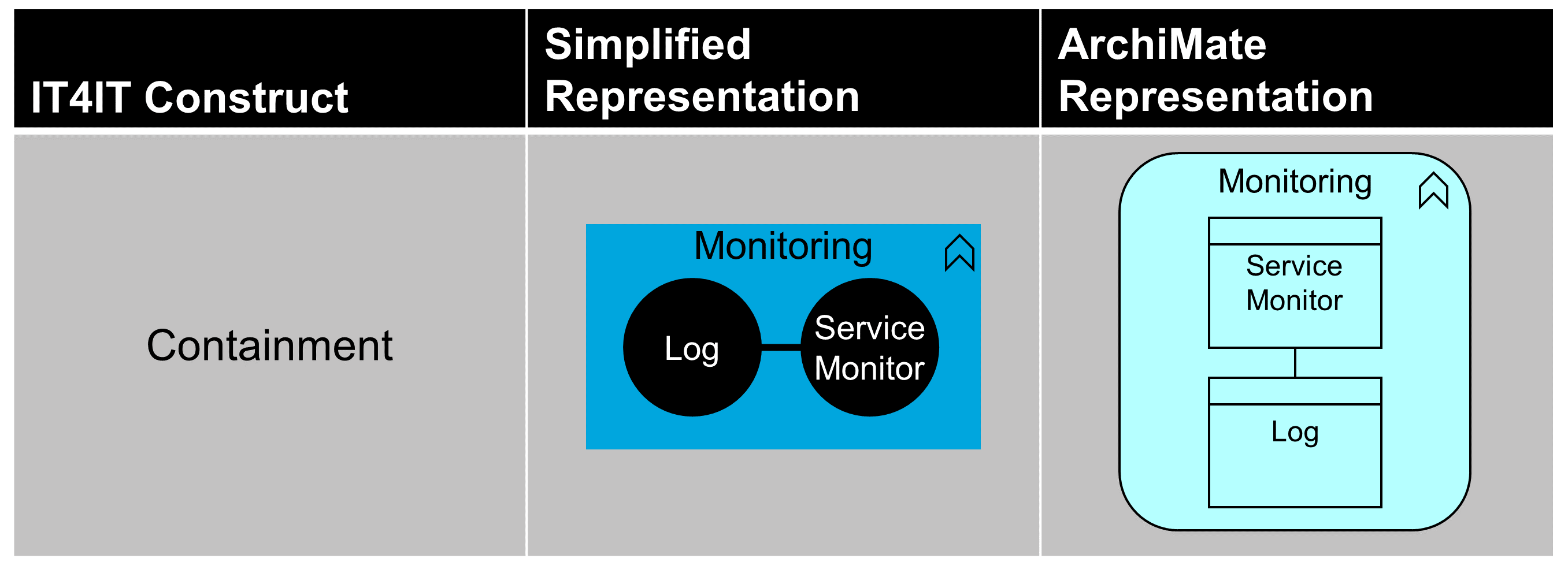
While a functional component may control one or more data object types, a single data object can only be controlled by one functional component. To communicate this visually, a notation that embeds the “controlled” data object in the functional component is used; see Figure 82.
Diagrams can be complex and require clear “visual syntax” to help the reader interpret the elements and their relationships. Text is used to describe the emphasis of the functional component. For that reason, the IT4IT Reference Architecture at Level 1 is depicted without data objects and relationships; see Figure 7.
As a general rule, the IT4IT Data Objects are named using:
-
A noun that describes the essence of what the data object is controlling
11.7.6. System of Record
A system of record is a synonym for a system that contains and/or controls authoritative source data.
The Lifecycle Data Objects represent the authoritative source data and/or master data for managing digital. In IT, “system of record” is a term that is commonly used as a synonym for an authoritative source system.
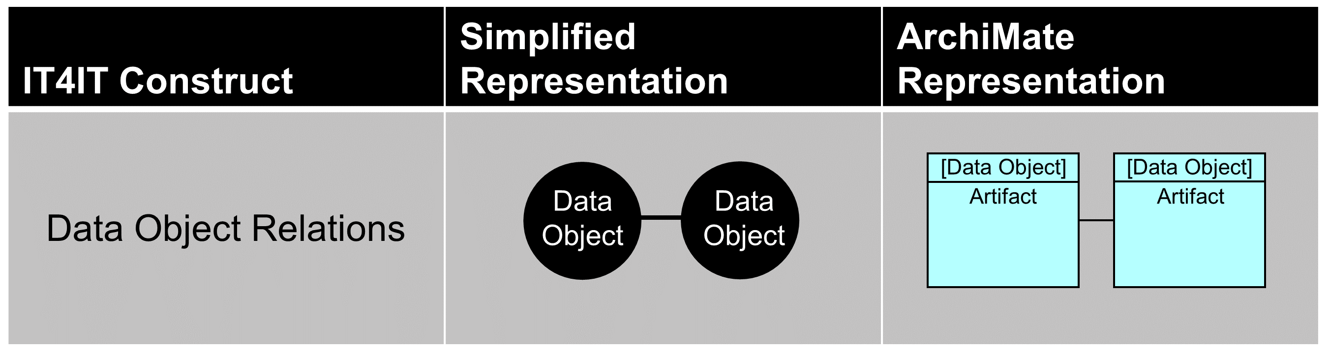
11.7.7. Relationships
An important aspect of the IT4IT Reference Architecture is to define not only the data objects but the essential relationships between them. The data objects, combined with their relationships and inter-dependencies, form the “system of record fabric” for digital management (see Figure 83 and Figure 84).
Note that in this document there are no defined “reflective” relationships, where a data object can relate to other data objects of its own type; for instance, the Digital Product data object relates to all the Digital Products on which it depends, the Service Offers can represent a hierarchy of offers, or Events can relate to Events to represent correlation. A future version of the IT4IT Standard will include these relations.
Notation and Naming
Abstraction Level 1 expresses essential relationships as lines between the participating data objects. Here, the simplified and ArchiMate notation are identical; a line connecting one data object with another.
Compliance with the prescribed system of record relationship mapping will ensure end-to-end traceability operationally and financially, and ensure Digital Product model integrity can be maintained across the lifecycle. This also eliminates the confusion and collisions that result from process re-engineering efforts that frequently occur within the various IT functions.
11.7.8. Digital Product Backbone Data Objects
The Digital Product Backbone data objects are key data objects in the IT4IT Reference Architecture that annotates an aspect of the Digital Product model in its planning, development, consumable, or running state. These data objects and their relationships form the Digital Product Backbone, which provides a holistic view of a Digital Product and includes the Digital Product, Product Design, Product Release, Desired Product Instance, and Actual Product Instance.
The IT4IT Standard collectively refers to all Digital Product Backbone data objects as the “Digital Product Backbone'”.
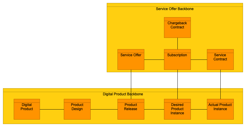
11.7.9. Service Offer Backbone Data Objects
The Service Offer Backbone data objects are key data objects in the IT4IT Reference Architecture that control and define the consumption of a Digital Product. These data objects and their relationships form the Service Offer Backbone and include the Offer, Subscription, Chargeback Contract, and Service Contract data objects.
The IT4IT Standard collectively refers to to all the Service Offer Backbone objects as the Service Offer Backbone; see Figure 85.
Note that Figure 85 is an abstraction and the relation between Service Offer and Product Release is via the Product Release Blueprint.
11.8. Concepts at Level 2: Value Stream Documentation
The value stream concept is introduced at Level 1, but is normatively defined at Level 2. In order to normatively define value streams, the following concepts are introduced:
-
Scenarios
-
Value stream stages
-
Stakeholders
Further, the normative definition of the IT4IT Value Streams refers to data objects, which are introduced and defined at Level 1.
11.8.1. Value Stream
In the normative definition of value streams, scenarios are defined for which the value stream is executed. This is complemented by defining the activities that are expected to happen as part of implementing the value stream; documented as value stream stages.
Note that the value stream stages of an IT4IT Value Stream are not considered to be a sequence of activities; value streams are abstract, and not a process description.
11.8.2. Scenario
A scenario defines a situation in which a given value stream should be triggered to add value to the overall Value Network.
The ArchiMate solution pattern for this is an “Outcome” motivational element.
11.8.3. Value Stream Stage
A value stream stage is a refinement of the value stream, and uses the same ArchiMate solution pattern: a Value Stream data object.
A value stream stage is defined in terms of
-
Entry and exit criteria
-
Main activities
-
Examples of participating stakeholders
-
Participating data objects and containing functions
11.8.4. Stakeholder
A stakeholder is a persona or role that an organization is expected to engage in a given value stream stage.
|
Note
|
The IT4IT Standard does not normatively define the needed stakeholders, but merely proposes possible stakeholders to engage. Stakeholders must be refined when the reference architecture is used to derive a concrete implementation architecture at Level 5. |
The ArchiMate solution pattern for this is a “Business Stakeholder” motivational element.
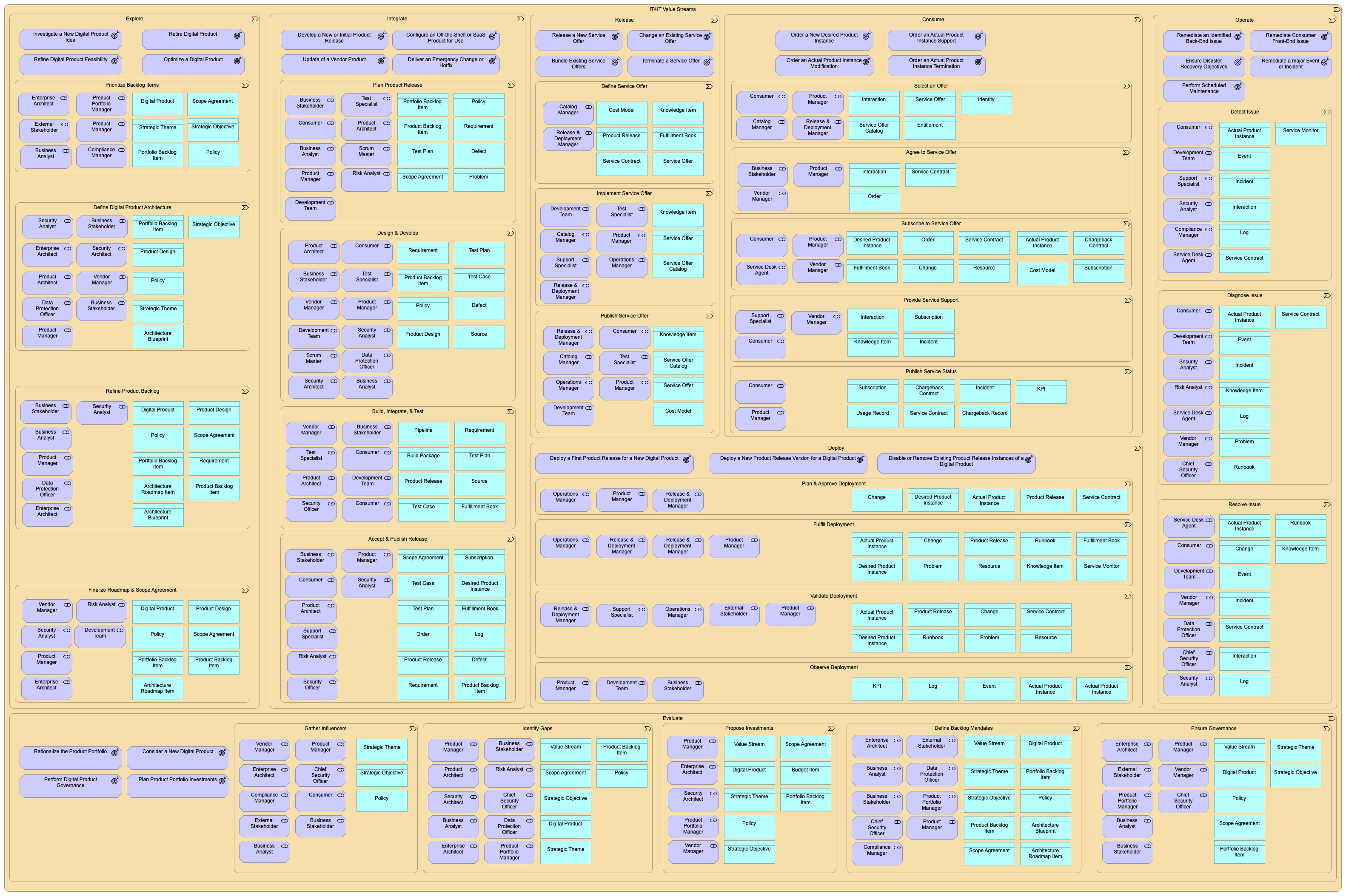
This leads to the ArchiMate structure of the seven IT4IT Value Streams in Figure 87. For more detail, see the definitions in Chapter 5.
11.9. Concepts at Level 3: Vendor-Independent Architecture
The normative definition of the IT4IT Value Streams at the Level 2 abstraction is complemented by the normative definition at Level 3 of:
-
Functional components
-
Data objects
-
Object relations
All of which have already been introduced at Level 1.
The normative definition of the functional components and data objects introduces a few more concepts:
-
Data objects including key attributes
-
Relationships between data objects are updated with cardinality information (e.g., one-to-one, one-to-many, many-to-many)
-
The concept of data flow between functional components is introduced
-
The data flows are grouped into record integrations and engagement integrations
11.9.1. Key Attributes
As described in Levels 1 and 2, data objects represent the data exchanged between functional components. At abstraction Level 3 it is important to specify the attributes of the objects that must be present (those deemed essential) in the exchange. Here, the minimum set of attributes required to maintain the integrity of the system of record fabric is defined. These attributes also contribute to the formation of the canonical data model that underpins the IT4IT Reference Architecture. Often, IT management products will provide more information/attributes, but at Level 3 only the vendor-independent minimum that all should include is defined.
Note that the specification of a key attribute for a data object only implies that the reference architecture insists that an implementation must support the attributes. It does not specify that every instance of the data object type must have a value associated with the attribute. For example, an approval data attribute will only be filled out if the approval has happened.
The most basic key attributes are a “unique identifier” and the “data object lifecycle status”. Often there will be attributes that identify relationships to other data objects in the IT4IT model.
Notation and Naming
The ArchiMate language does not have a means to model the concept of attributes. The IT4IT Standard documents the attributes in the description of the individual key data objects. Attributes are documented as a list of name/description parts.
The naming of attributes is without prepended or appended data to the object name. So, in the Incident example above, the IT4IT Standard does not define the identifier attribute for the Incident object to be “IncidentId” or the name attribute to be “IncidentName”. It simply has attribute names such as “Id” and “Name”. If there is a need to specify the Id of a particular data object, then the usual dot notation common in database systems is used:
-
The “Id” of the Incident data object can be referred to as “Incident.Id”
The IT4IT Standard aims to re-use attribute names that denote the same thing across data object definitions to facilitate the ease of implanting systems using inheritance and to ease the management of different objects in a coherent way.
11.9.2. Cardinality
Cardinality (sometimes referred to as “multiplicity”) describes the number of allowable relations a given element can have with elements of a given other type.
For example, there is a one-to-n (1:n) relationship between “Order” and “Change” data objects. This indicates that a single order can result in multiple change requests. In the instance of a “laptop” Order, a change request might require a request for the laptop to be allocated and configured and a further change for a corporate user account to be security configured for mobile work. Therefore, one Order generated multiple Change objects, and relations must be maintained to each.
The IT4IT Reference Architecture only defines the key relationships – those that contribute to the advancement of the service lifecycle. There are other relationships that may be needed to satisfy the specific policies, processes, or capabilities but they are not considered to be part of the prescriptive guidance. Further, relationships may be maintained simply to optimize the implementation; for example, the Actual Product Instance might have a relationship back to the Digital Product data object, of which it is an instance. This relationship could be derived through the relationships across the Digital Product Backbone. The normative IT4IT Standard does not make recommendations for such optimizations.
In UML, the concept of multiplicity extends the definition/understanding/concept of cardinality by including more information on participation; i.e., what relationships must exist, or not. The IT4IT Standard does not specify multiplicity.
The IT4IT Standard only differentiates between three types of cardinality, as shown in Table 1.
| IT4IT Cardinality | Representation | Notes |
|---|---|---|
One-to-no more than one (also called one-to-one) |
1:1 |
Means “can” have a relationship. “Must” have a relationship is not specified. In UML this would be a 0..1 : 0..1 relation. |
One-to-many |
1:n or n:1 |
As above, there might not be a relationship or there might be a relationship to only one. In UML this would be a 0..1 : * relation. |
Many-to-many |
n:m |
Both objects in a relationship “can” have relations to several other objects. In UML this would be a * .. * relation. |
Notation and Naming
The ArchiMate language does not allow the specification of cardinality in relationships, which means that cardinality is not represented in diagrams in the normative IT4IT Standard. To resolve this, data object relationships are documented in the description of the relationship in a section named “Key Data Object Relationships”.
It lists all the relations and for each in the following form:
-
<DataObject> to <DataObject> (x:y): <description of why the relation is created>
This gives the four possible notations, illustrated with four examples from the standard:
-
Problem to Defect (1:1): indicates that an identified Problem can be the source of one Defect, and similarly a Defect can be related to a Problem (but not multiple Problems)
-
Incident to Change (1:n): indicates that a single Incident can relate to several Change objects (indicating that potentially more than one Change was done in order to remediate the Incident)
On the other hand, a given Change object can only relate to a single Incident; e.g., you can track which Incident was the reason for the Change to be created
-
Change to Incident (n:1): the opposite of the above when documenting the Change data object as opposed to documenting the Incident data object
-
Incident to Event (n:m): indicates that any given Event can relate to several Incidents (indicating that several reported Incidents are really all related to the same operational Event), and each Incident can relate to several Events (to indicate that multiple Events are occurring as a consequence of the same Incident)
11.9.3. Data Flow
A data flow describes the flow of information between functional components. The technique used to facilitate the flow is not specified. The reason for adding the data flow information to the Level 3 diagrams is to expose the need for integration and data sharing. It also helps to demonstrate the dependencies between functional components and how they can work together to deliver value.
|
Note
|
Data flows do not represent process. Data flows represent core integrations between components that ensure data between modules is synchronized to ensure the information model is maintained. |
The data flow arrow originates from the functional component that would normally trigger the exchange of information. This does not imply that information is only exchanged in that direction.
An example of a data flow can be seen in Figure 88.
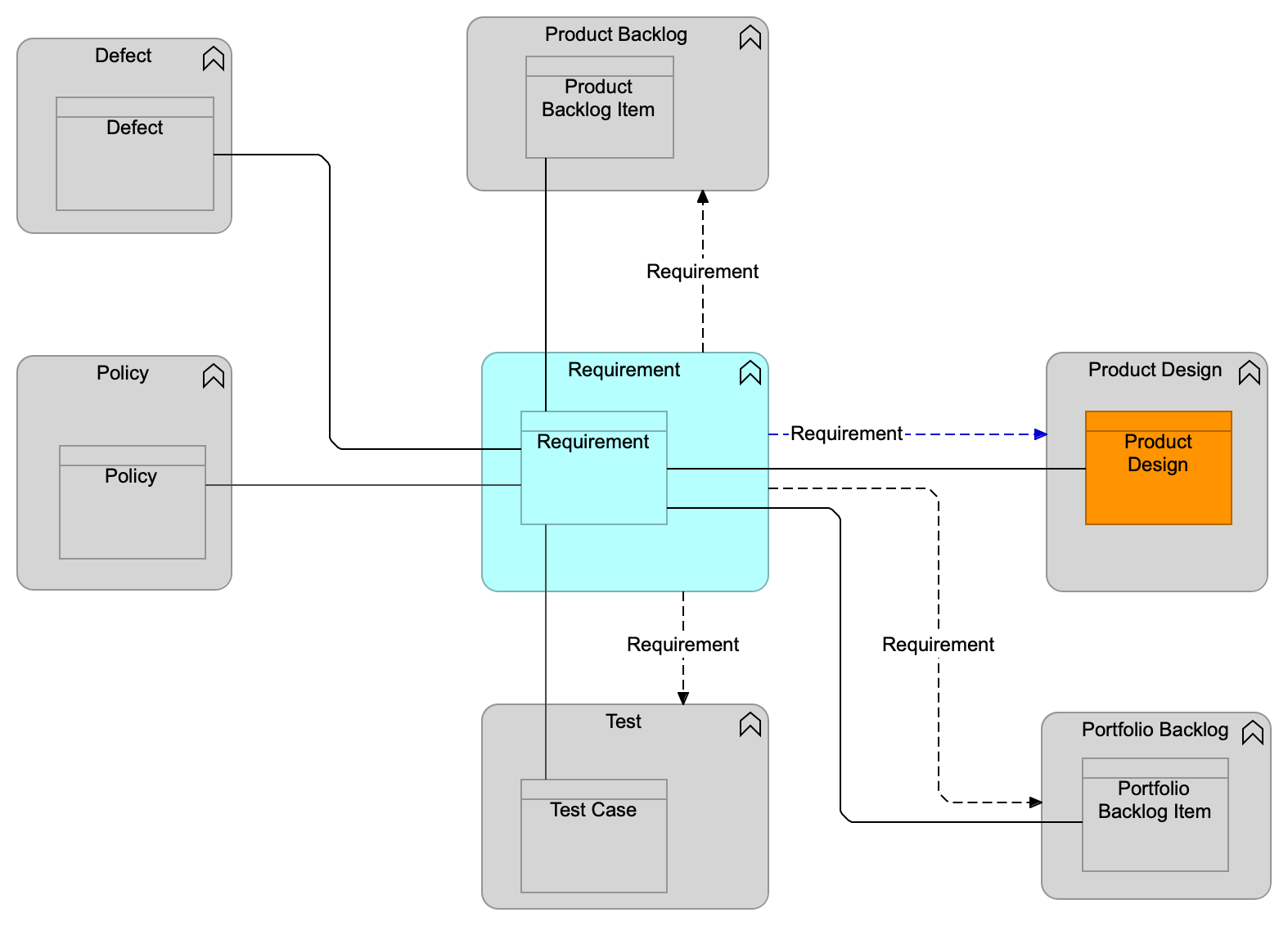
Figure 88 indicates a data flow of requirement data from the Requirement functional component to the Test functional component. There is also a data flow of test result data from the Test functional component to the Defect functional component. These two flows are used to maintain the relationships between the corresponding data objects.
Finally, there is a data flow from the Pipeline functional component to the Test functional component indicating that the Pipeline functional component engages with the Test functional component. The data flow indicates that a specific test needs to be triggered for execution.
As is seen in Figure 88, an arrow is used for representing data flows. As indicated, there are two types of data flows:
-
System of record data flows: these establish system of record integrations and are essential for maintaining a consistent and traceable information model for digital management
-
Engagement data flows: these represent integrations that are useful for efficiently implementing the value streams that orchestrate the use of many of the IT4IT components
11.9.4. System of Record Integration
In Level 1, key data objects and their relationships are introduced. In Level 2, how data objects are consumed or created/updated by the value streams is described. In Level 3, all the necessary key data objects and relationships are defined to form a consistent and traceable information model for managing Digital Products.
In order for the system of record relationships to be sustained over the course of the product lifecycle, integrations between functional components controlling the key data objects must be well defined. This requires that some data flows need to be “refined” into system of record integration specifications. These specifications become part of the normative IT4IT Standard.
For a data flow to be refined into a system of record integration, the following conditions must be satisfied:
-
The data flow creates a relationship/dependency between two data objects in the functional components involved in the data flow
-
The two data objects must have a direct relationship to be maintained
-
The lifecycles of the two data objects are interlocked; updates to one data object can have consequences on the other data object
The reason for defining these integrations as part of the architecture is to ensure the integrity of the system of record fabric and the service model. IT organizations are likely to implement products from multiple suppliers for their IT4IT Reference Architecture, and without this specification there is no way to ensure consistency in data flows.
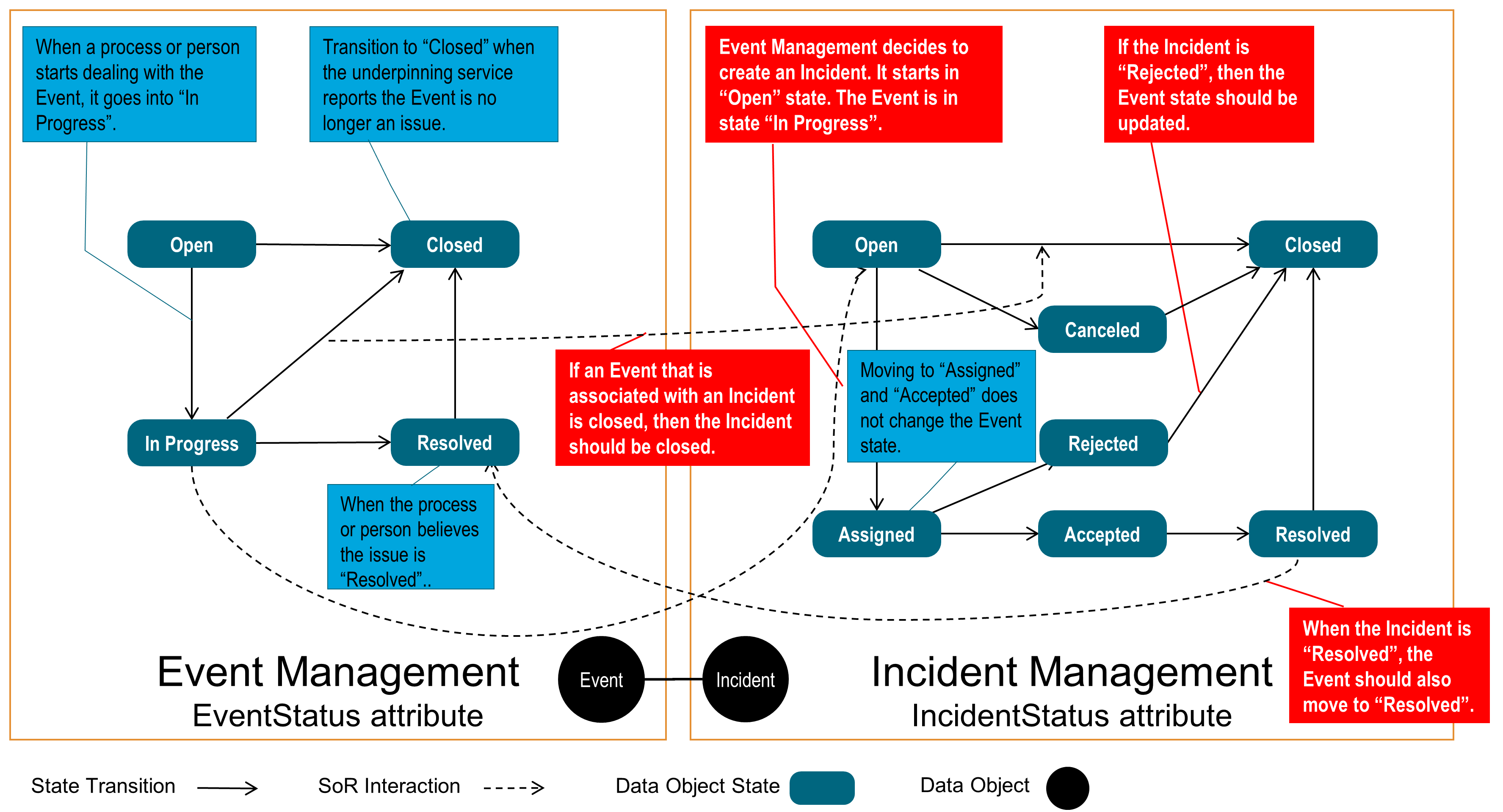
A system of record integration is depicted in Figure 89. This figure provides an illustrative example that describes the state dependency between the “Event” and “Incident” data objects. Here, Events generate Incidents, which results in a relationship and dependency between these two data objects.
11.9.5. SoE Integration
Relationships are also formed between functional components to enable humans and machines to interact with and/or take action on the data objects. These relationships are called “System of Engagement” integrations (experience-centric integration) and are derived from value stream use-cases and user stories. They are offered as guidance rather than prescriptive practices; the intent being to demonstrate to the reader how data object relationships stimulate and/or are affected by human-to-machine and machine-to-machine interactions.
Notation and Naming
At Level 3, the normative notation depicts system of record integrations using a black dotted line with solid end-arrow accompanied by the name of the data object that is transferred to create the relationship. No subsequent information is shown as being passed on an ongoing basis to maintain or update either data object. The formal notation in the ArchiMate language uses the collaboration and interaction concepts.
SoE integrations are rendered as a blue dotted line with a solid end-arrow, with a name that illustrates which type of engagement or process action is responsible for triggering the integration/data flow.
11.10. Concepts at Level 4 and Level 5
Level 4 and Level 5 of an IT4IT architecture are not part of the normative standard.
Level 4 is used to represent reference architectures built by vendors and system integrators as a refinement of the normative IT4IT Standard.
Level 5 is used to refine Level 4 (or Level 3) reference architectures into a concrete implementation architecture.
Levels 4 and 5 are not owned and controlled by The Open Group but by the consumers of the IT4IT Standard.
For example, vendors might add essential services to the baseline or add functional components to differentiate their product or offering. The principle to be applied here is that whatever is added should build from and add to, but not change the prescriptive model defined in Levels 1 to 3.
|
Note
|
In The Open Group IT4IT Forum, some examples of Level 4 and Level 5 architectures have been developed as guiding material. |
11.10.1. Level 4 – Vendor and System Integrator Extensions
Abstraction Level 4 is where the architecture becomes more Product Design and implementation-oriented. Here, for example, providers of IT management products and services can design/specify their service, interface, and exchange models, which should be derived from Level 3 content. Other examples of Level 4 content might include:
-
Defining extensions to the standard: “these key attributes are being used, but these are added for the following reasons …”
-
Adding data objects: “these non-key data objects were added, and are using the same notation style to reflect how they build off the baseline architecture”
-
Additional notations: “the ArchiMate language is used for explaining scenarios and UML for the data models”
-
Introduction of process: might introduce/model practitioner-level processes within scenarios
-
Canonical data model: might introduce the vendor-specific canonical data model for their IT management products
-
Integrations: might specify the techniques/methods used in implementing system of record integrations
Regardless of the how the vendor chooses to adapt and implement the architecture, it must be able to be mapped back into what is specified at Levels 1 to 3.
11.10.2. Capabilities
A capability is the ability of an organization to produce an outcome of value through the utilization of people, processes, and technology. A list of capabilities with a high level of granularity is being compiled. These come from ITIL, COBIT, SAFe, PMBOK, and other industry sources. It is not the focus or intent of this document to redefine or modify existing work that has been done around such IT capabilities, but, as a non-normative work, a comprehensive list is being compiled that defines the relationships to functional components.
Capabilities can be viewed as a refinement of the Level 2 normative functional groups of the IT4IT Reference Architecture. In the solution pattern/metamodel, the functional components belong to a Level 2 group but will relate to one or several capabilities.
Note that in the IT4IT Standard, Version 2.1, and other previous IT4IT Standard versions, capabilities were named “Capability Disciplines” to relate to the “Discipline” concepts of ITIL, Version 3.
Notation and Naming
While capabilities are not part of the normative IT4IT Reference Architecture, we recommend to use the ArchiMate notation to describe them for consistency across the architecture.
11.10.3. Essential Services
In the IT4IT Reference Architecture, the essential service concept describes a means of facilitating integration between functional components or to take action on a data object; e.g., Create, Read, Update, Delete (CRUD). Essential services are typically implemented as an API, web service, or microservice with a well-defined set of parameters. The goal of essential services is to eliminate the need for point-to-point integrations between IT management products. They are defined by examining the data objects and specifying the attributes, parameters, etc.
These essential services will be used to implement the data flows and the processes that are deemed necessary to deliver optimized value streams.
Notation and Naming
Essential services can be modeled in the ArchiMate language using the “Application Service” construct. In the informal notation at Level 4 they are depicted as an oval inside a functional component element, as in the scenario example given in Figure 90.
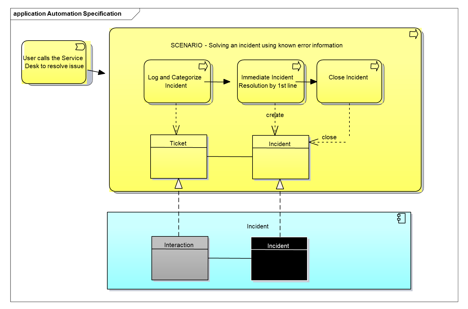
11.10.4. Scenarios and Processes
In the IT4IT Reference Architecture, a scenario is a narrative that describes foreseeable interactions of user roles (or “actors”) and a system (or functional component). The term is analogous with “epic” or “theme” in Agile development methodologies. Scenarios are used to explain, enhance, or modify the reference architecture and are described using a structured template that includes a formal notation that can be expressed in the ArchiMate language. This enables readers to consume information more easily, as multiple organizations may produce and/or contribute to scenarios over time.
The following list is an example of the “scenario master document content”:
-
Introduction: a high-level description of the scenario to be described along with the goal to be achieved
-
Requirements: model the properties of the elements that are needed to achieve the “ends” that are modeled by the goals; in this respect, requirements represent the “means” to realize goals
-
Process flow: an explanation of the process flow in the organization; this example explains how an Incident is handled using existing knowledge
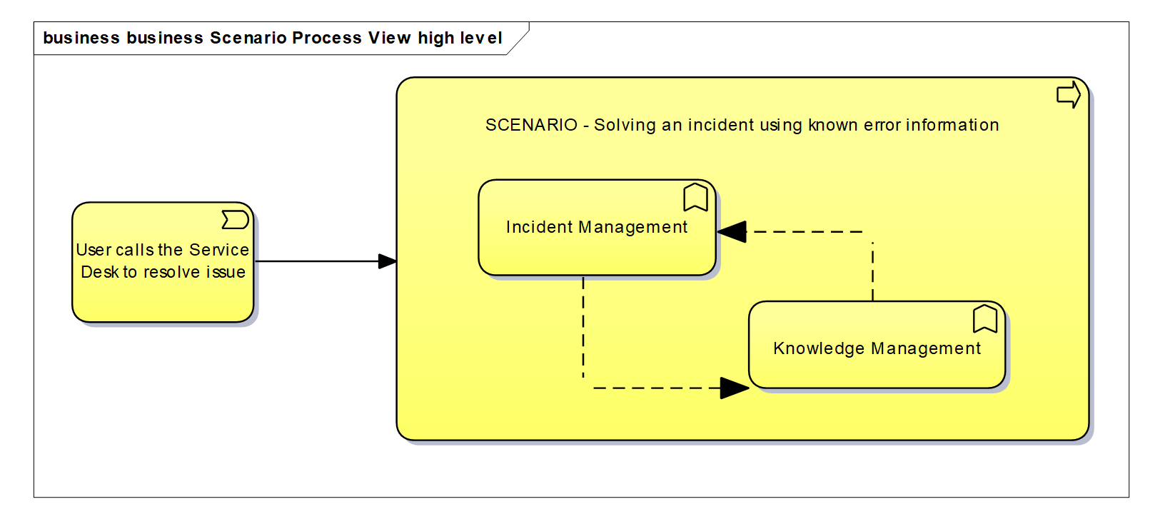
-
Automation specification using the reference architecture: explains how the process is to be supported by the reference architecture
In the example shown in Figure 91, two views would be created: one showing an Incident Management capability and another view for the Knowledge Management capability. The view should provide more information on how the functional components are aligned with the capabilities to automate the scenario:
-
Essential services supporting the scenario; see Figure 90
-
Data objects and key attributes: describes the data objects that are involved and the attributes of the data objects that are needed or impacted
11.10.5. Level 5 – Implementation Architecture
The full power of the ArchiMate language can be used to specify an actual current or future state implementation of the IT4IT Reference Architecture.