4. Generic Metamodel
|
Note
|
The relationships shown in the metamodel figures are not to be confused with ArchiMate relationships. They are metamodel relationships expressing the structure of the language rather than a model in the language. |
4.1. Behavior and Structure Elements
The main hierarchy of behavior and structure elements of the ArchiMate language is presented in the metamodel fragment of Figure 4. It defines these elements in a generic, layer-independent way. Note that most of these elements (the white boxes) are abstract metamodel elements; i.e., these are not instantiated in models but only serve to structure the metamodel. The notation presented in this chapter is therefore the generic way in which the specializations of these elements (i.e., the elements of the different architecture layers) are depicted.
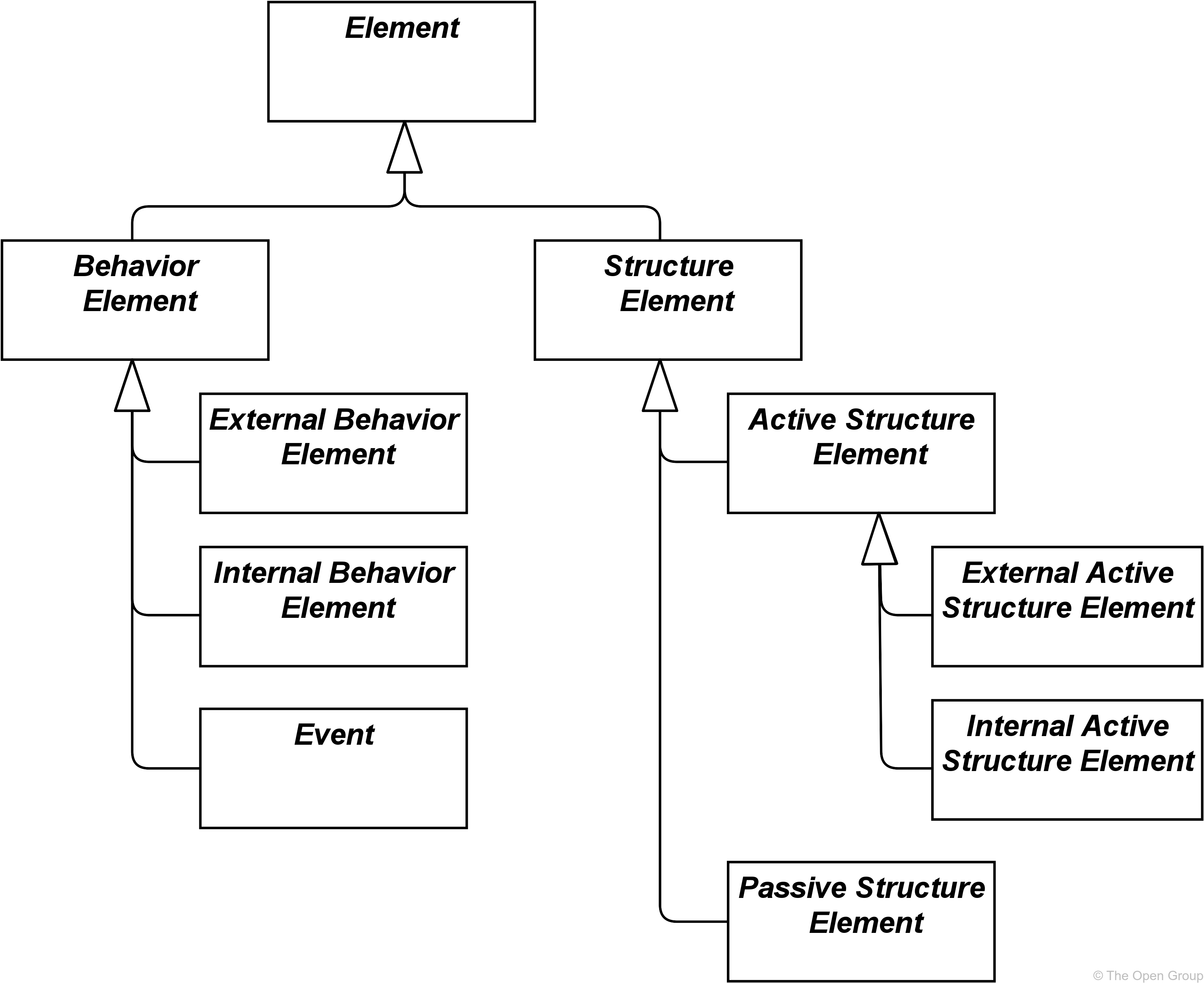
This generic metamodel fragment consists of two main types of elements: structure (“nouns”) and behavior elements (“verbs”).
Structure elements can be subdivided into active structure elements and passive structure elements. Active structure elements can be further subdivided into external active structure elements (also called interfaces) and internal active structure elements.
Behavior elements can be subdivided into internal behavior elements, external behavior elements (also called services), and events.
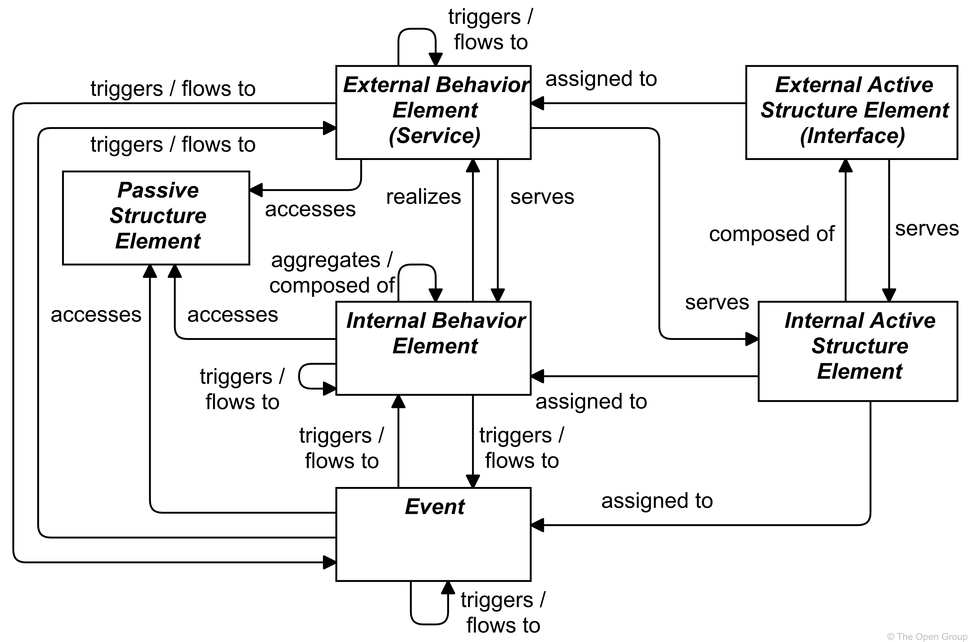
Figure 5 specifies the main relationships between the behavior and structure elements defined above. For an explanation of the different types of relationships see Chapter 5. In this and other metamodel figures, the label of a relationship signifies the role of the source element in the relationship; e.g., a service serves an internal behavior element.
|
Note
|
This figure does not show all permitted relationships; every element in the language can have composition, aggregation, and specialization relationships to elements of the same type. Furthermore, there are indirect relationships that can be derived, as explained in Section 5.7. The full specification of permitted relationships can be found in Appendix B. |
|
Note
|
This figure is to be read as a generic template for the layers of the ArchiMate core (see Section 3.4), but is not applied directly. Each layer defines its own specialized version of this. |
4.1.1. Active Structure Elements
Active structure elements are the subjects that can perform behavior. These can be subdivided into internal active structure elements; i.e., the business actors, application components, nodes, etc., that realize this behavior, and external active structure elements; i.e., the interfaces that expose this behavior to the environment. An interface provides an external view on the service provider and hides its internal structure.
An internal active structure element represents an entity that is capable of performing behavior.
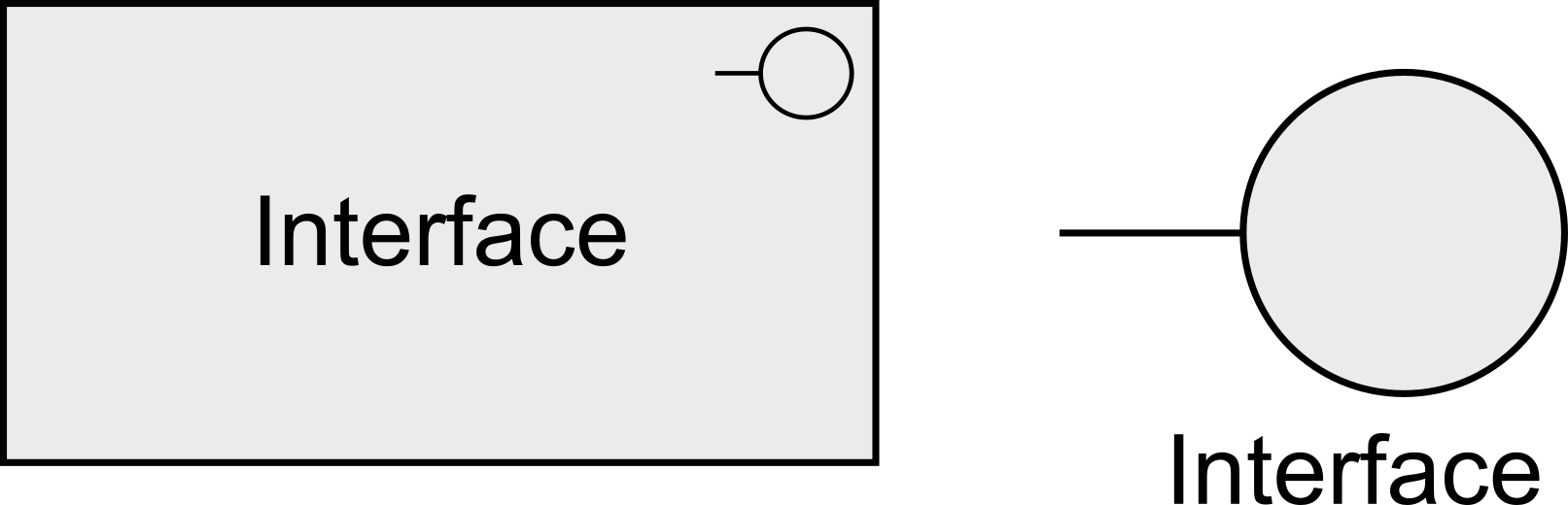
Active structure elements are denoted using boxes with square corners and an icon in the upper-right corner, or by the icon on its own.
An external active structure element, called an interface, represents a point of access where one or more services are provided to the environment.
4.1.2. Behavior Elements
Behavior elements represent the dynamic aspects of the enterprise. Similar to active structure elements, behavior elements can be subdivided into internal behavior elements and external behavior elements; i.e., the services that are exposed to the environment.
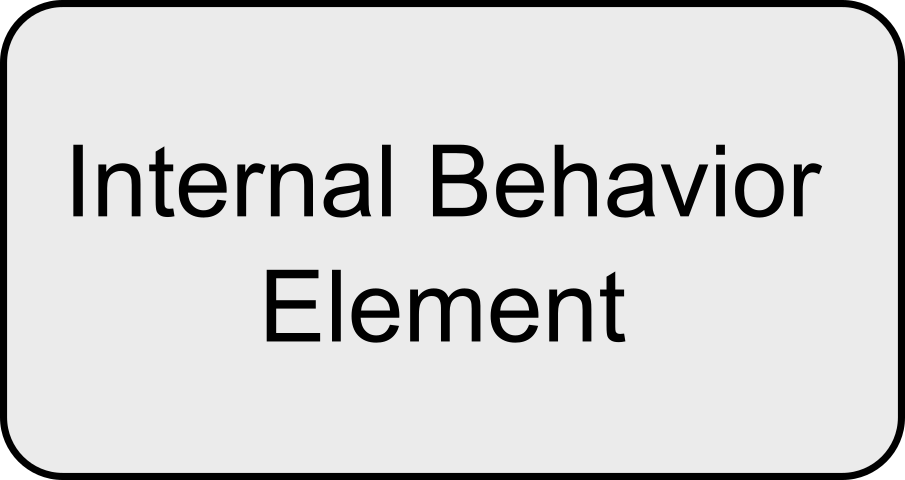
An internal behavior element represents a unit of activity that can be performed by one or more active structure elements.
Behavior elements are denoted in the standard iconography using boxes with round corners and an icon in the upper-right corner, or by the icon on its own.
An external behavior element, called a service, represents an explicitly defined exposed behavior.
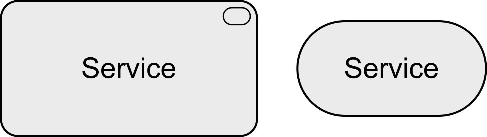
Thus, a service is the externally visible behavior of the providing system, from the perspective of systems that use that service; the environment consists of everything outside this providing system. The value offered to the user of the service provides the motivation for the existence of the service. For the users, only this exposed behavior and value, together with non-functional aspects such as the quality of service, costs, etc., are relevant. These can be specified in a contract or Service-Level Agreement (SLA). Services are accessible through interfaces.
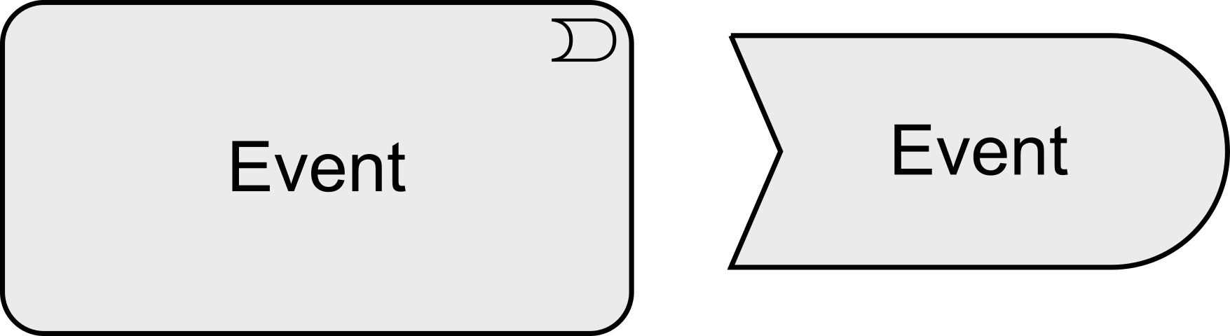
In addition to this, a third type of behavior element is defined to denote an event that can occur; for example, to signal a state change.
An event represents a state change.
An event may have a time attribute that indicates the moment or moments at which the event happens. For example, this can be used to model time schedules.
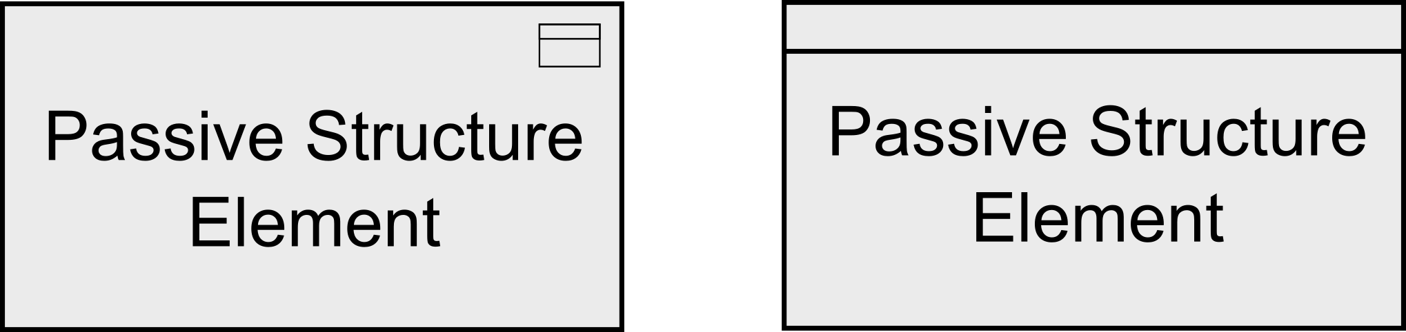
4.1.3. Passive Structure Elements
Passive structure elements can be accessed by behavior elements.
A passive structure element represents an element on which behavior is performed.
A passive structure element is a structural element that cannot perform behavior. Active structure elements can perform behavior on passive structure elements. Passive structure elements are often information or data objects, but they can also represent physical objects.
4.2. Specializations of Structure and Behavior Elements
The specializations of core elements are summarized in Figure 12. Within each layer, it is permitted to use composition and aggregation relationships between processes, functions, and interactions; e.g., a process can be composed of other processes, functions, and/or interactions.
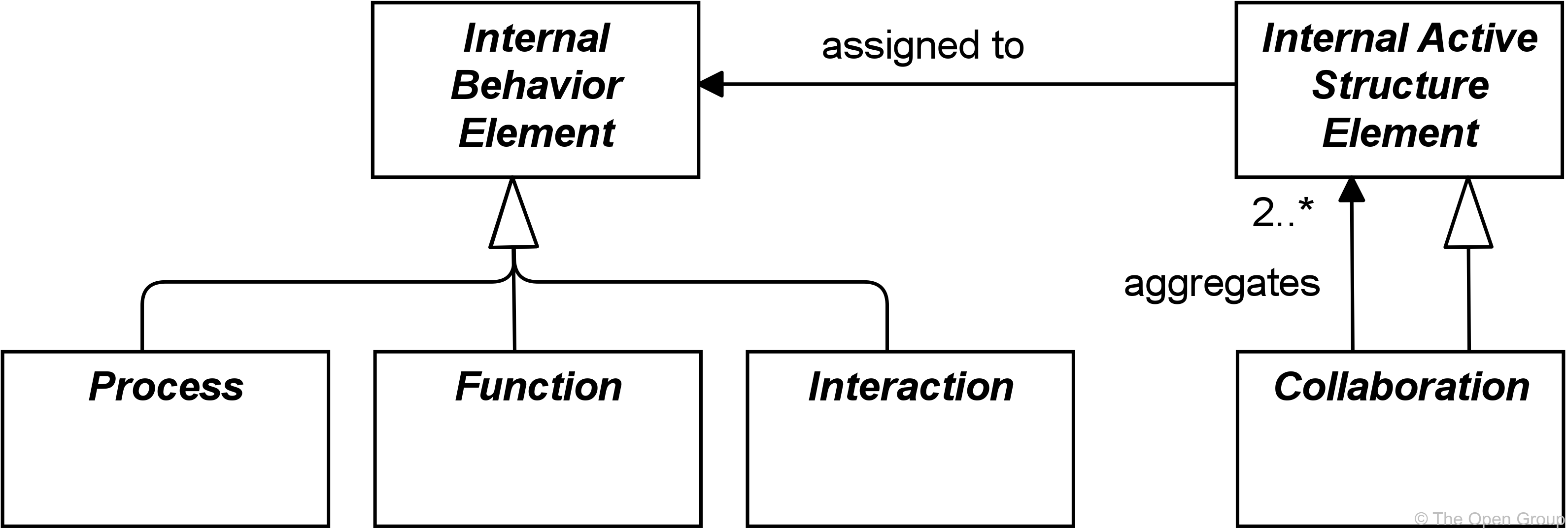
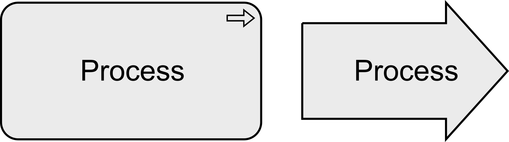
For individual internal behavior elements, a distinction is made between processes and functions.
A process represents a sequence of behaviors that achieves a specific result.
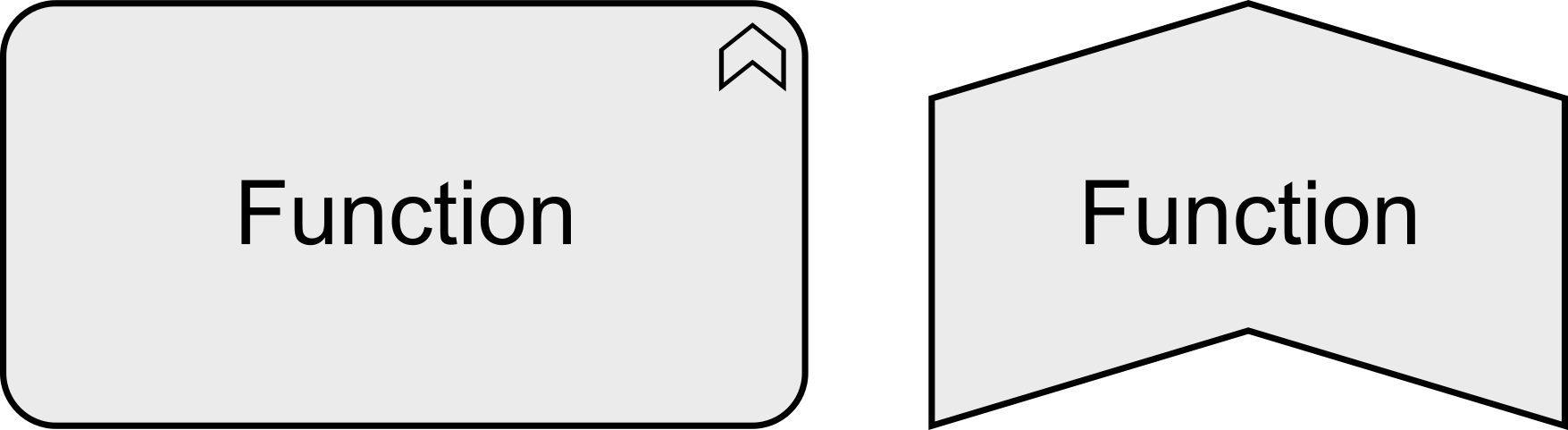
A function represents a collection of behavior based on specific criteria, such as required resources, competencies, or location, and is managed, performed, or implemented as a whole.
Internal behavior elements can be composed of or aggregate other internal behavior elements, as shown in Figure 5. This means, for instance, that processes can be composed of functions and vice versa.
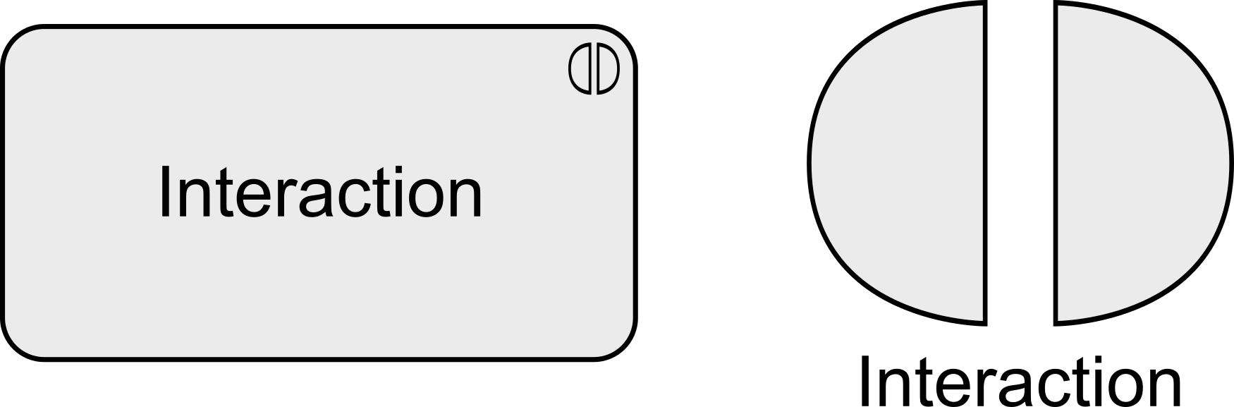
The collective nature of a behavior can be modeled either implicitly (several active structure elements assigned to the same internal behavior via an and junction) or explicitly through the use of a collective internal behavior element, interaction, that is performed by (a collaboration of) multiple active structure elements.
An interaction represents a unit of collective behavior that must be performed by two or more internal active structure elements, either assigned directly or aggregated in a collaboration.
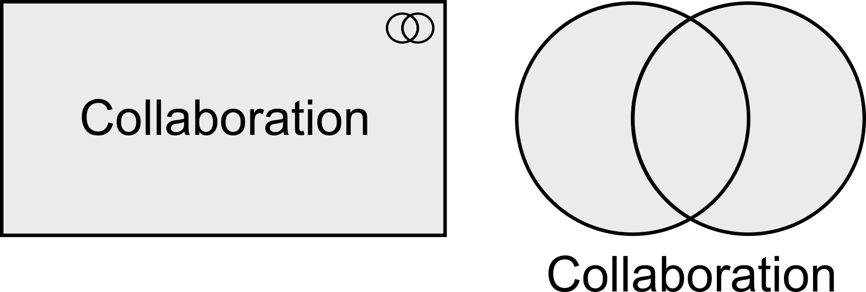
A collaboration represents an aggregate of two or more internal active structure elements, working together to perform some collective behavior.
4.3. Summary of Structure and Behavior Elements
Table 1 gives an overview of the core elements, their definitions, and their default graphical notation. But note that most of these elements are abstract; they are not used in models but only their descendants in the different layers of the ArchiMate language.
| Element | Specializations | Definition | Notation |
|---|---|---|---|
Active Structure |
|||
Internal Active Structure Element |
Represents an entity that is capable of performing behavior. |
|
|
Collaboration |
Represents an aggregate of two or more internal active structure elements, working together to perform some collective behavior. |
|
|
Interface (External Active Structure Element) |
Represents a point of access where one or more services are exposed to the environment. |
|
|
Behavior |
|||
Internal Behavior Element |
Represents a unit of activity that can be performed by one or more active structure elements. |
|
|
Process |
Represents a sequence of behaviors that achieves a specific result. |
|
|
Function |
Represents a collection of behavior based on specific criteria, such as required resources, competencies, or location, and is managed, performed, or implemented as a whole. |
|
|
Interaction |
Represents a unit of collective behavior that must be performed by two or more internal active structure elements, either assigned directly or aggregated in a collaboration. |
|
|
Service (External Behavior Element) |
Represents an explicitly defined exposed behavior. |
|
|
Event |
Represents a state change. |
|
|
Passive Structure |
|||
Passive Structure Element |
Represents an element on which behavior is performed. |
|
|
4.4. Motivation Elements
The core elements of the ArchiMate language focus on describing the architecture of systems that support the enterprise. They do not cover the elements which, in different ways, drive the design and operation of the enterprise. These motivation aspects correspond to the “Why” column of the Zachman framework [5].
Several motivation elements are included in the language: stakeholder, value, meaning, driver, assessment, goal, outcome, principle, and requirement, which in turn has constraint as a subtype. In this section, the generic motivation element is introduced. The more specific motivation elements are described in Chapter 6.
The motivation elements address the way the Enterprise Architecture is aligned to its context, as described by these intentions.
A motivation element represents the context of or reason behind the architecture of an enterprise.
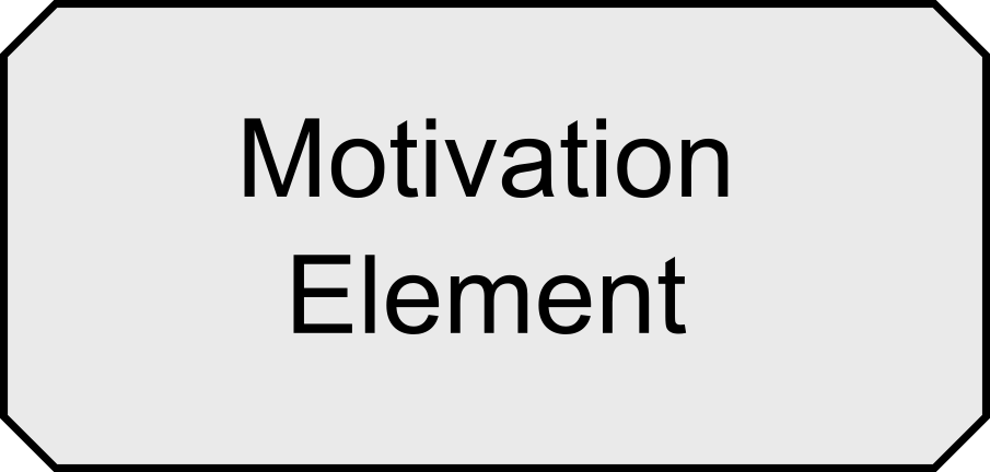
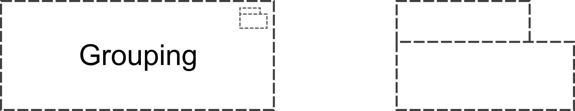
Motivation elements are usually denoted using boxes with diagonal corners.
| Element | Definition | Notation |
|---|---|---|
Motivation Element |
Represents the context of or reason behind the architecture of an enterprise. |
|
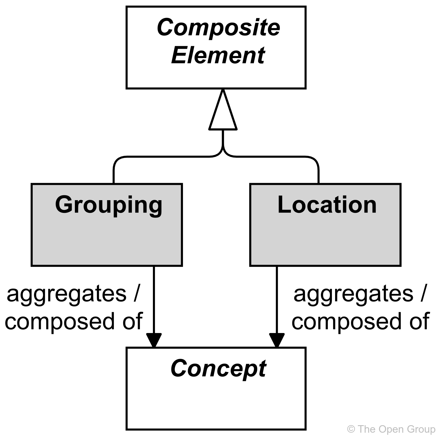
4.5. Composite Elements
Composite elements consist of other concepts, possibly from multiple aspects or layers of the language. Grouping and location are generic composite elements (see Figure 18). Other composite elements include Product (see Section 8.5.1) and Plateau (see Section 12.2.4). Composite elements can themselves aggregate or compose other composite elements.
4.5.1. Grouping
The grouping element aggregates or composes concepts that belong together based on some common characteristic.
The grouping element is used to aggregate or compose an arbitrary group of concepts, which can be elements and/or relationships of the same or of different types. An aggregation or composition relationship is used to link the grouping element to the grouped concepts. Grouping elements can also have other relationships to and from them, as shown in Appendix B.
Concepts may be aggregated by multiple (overlapping) groups.
One useful way of employing grouping is for modeling Architecture and Solution Building Blocks (ABBs and SBBs), as described in the TOGAF framework [4].
Another useful application of grouping is for modeling domains. For example, the TOGAF framework [4] Glossary of Supplementary Definition defines Information Domain as: “grouping of information (or data entities) by a set of criteria such as security classification, ownership, location, etc. In the context of security, Information Domains are defined as a set of users, their information objects, and a security policy”.
|
Note
|
The use of grouping is not to be confused with creating views on the architecture (Section 13.3). Although like a view it comprises concepts that belong together for some reason, it does not provide a separate visualization of these concepts. Moreover, groupings are used within architecture views to provide additional structure to an architecture model and its visualization. |
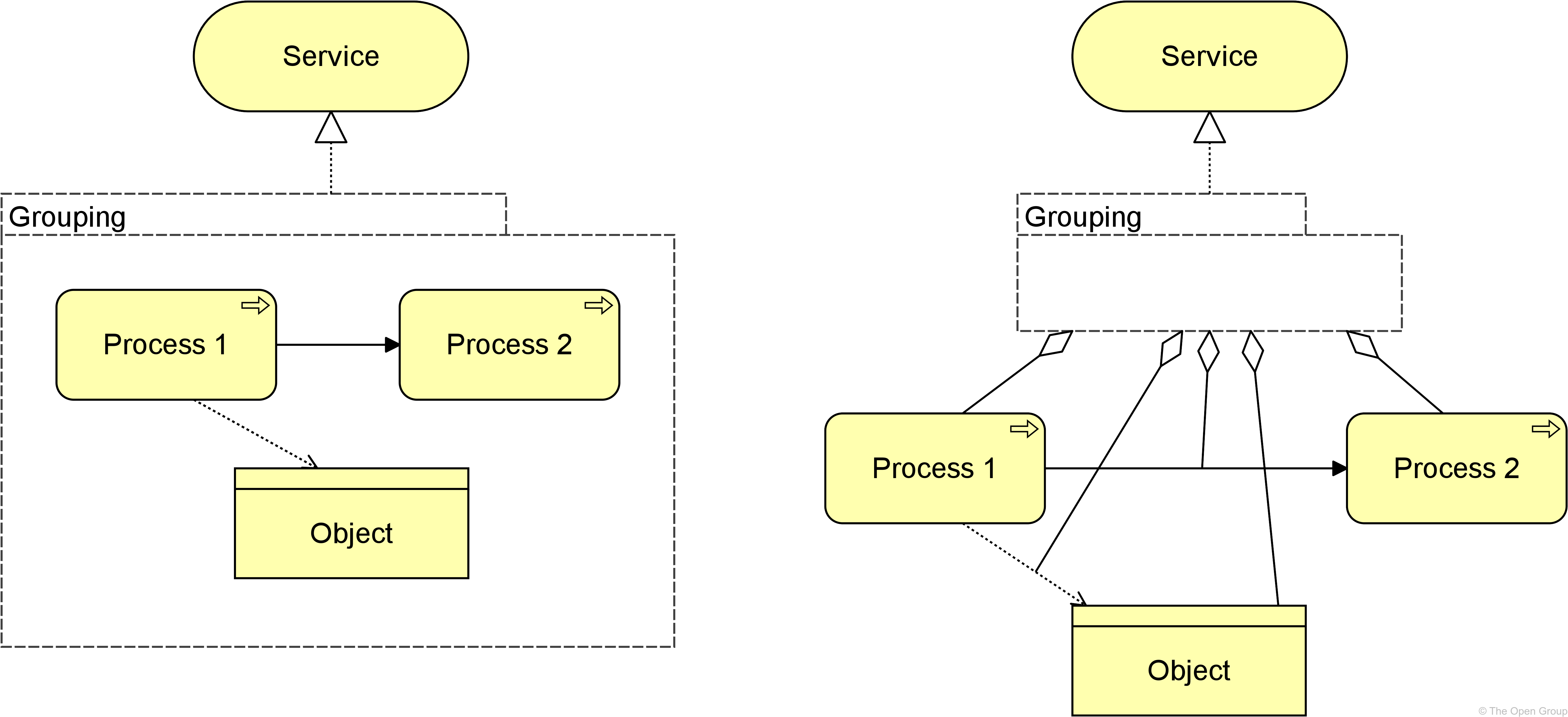
Example
|
Note
|
The semantics of grouping imply that a relationship from or to a group should be interpreted as a collective relationship with the group’s contents. In the example, the implied meaning is that the contents of the group together, or parts thereof, realize the service. However, this is not always easily expressed in simple derivable relationships. |
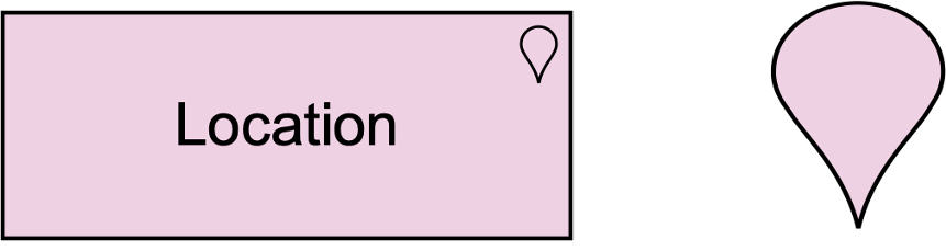
4.5.2. Location
A location represents a conceptual or physical place or position where concepts are located (e.g., structure elements) or performed (e.g., behavior elements).
The location element is used to model the places where (active and passive) structure elements such as business actors, application components, and devices are located. This is modeled by means of an aggregation relationship from a location to structure element. A location can also aggregate a behavior element, to indicate where the behavior is performed. This element corresponds to the “Where” column of the Zachman framework [5].