5. Relationships and Relationship Connectors
In addition to the generic elements outlined in Chapter 4, the ArchiMate language defines a core set of generic relationships, each of which can connect a predefined set of source and target concepts (in most cases elements, but in a few cases also other relationships). Many of these relationships are “overloaded”; i.e., their exact meaning differs depending on the source and destination concepts that they connect.
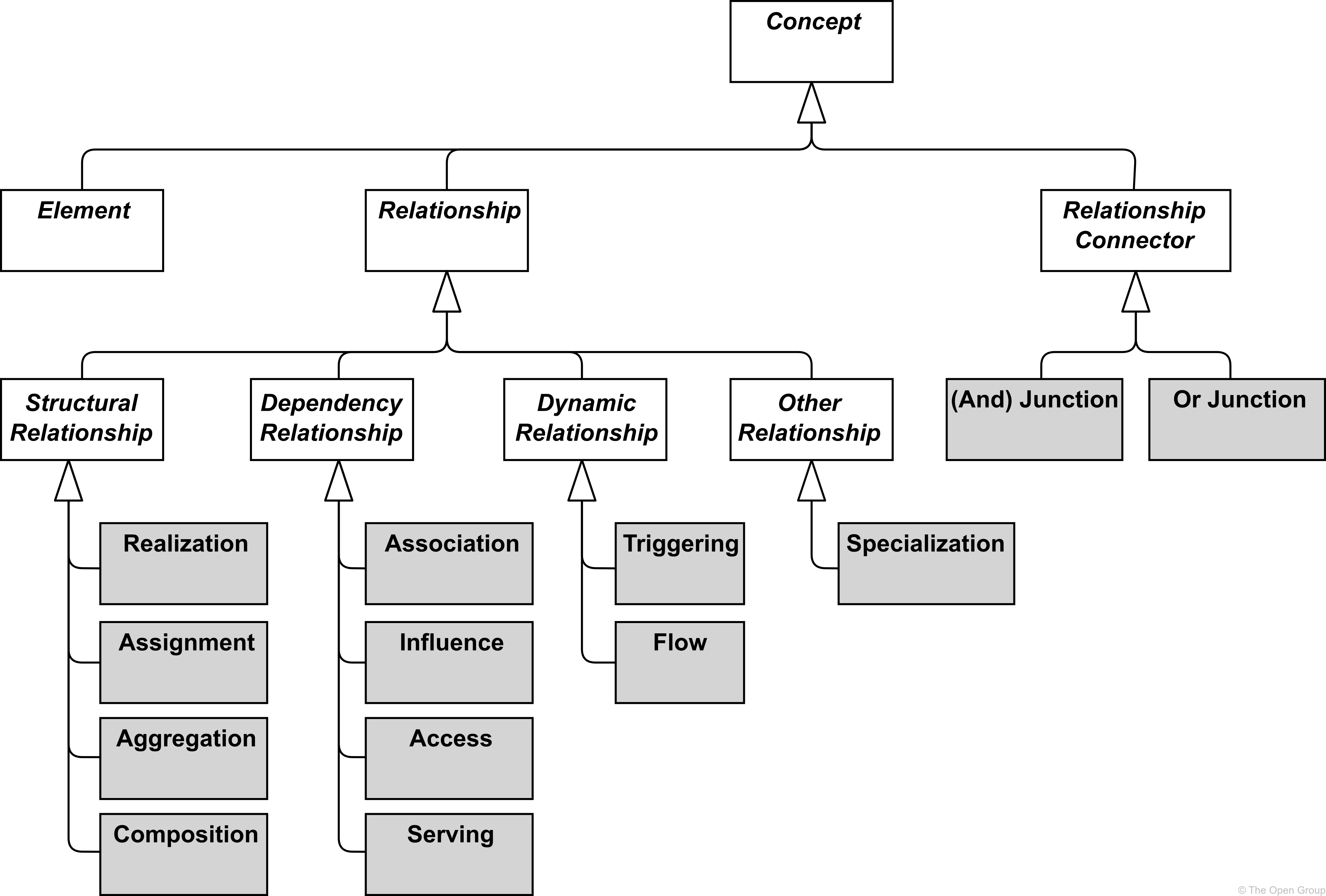
The relationships are classified as follows (see Figure 21):
-
Structural relationships, which model the static construction or composition of concepts of the same or different types
-
Dependency relationships, which model how elements are used to support other elements
-
Dynamic relationships, which are used to model behavioral dependencies between elements
-
Other relationships, which do not fall into one of the above categories
Each relationship has exactly one “from” and one “to” concept (element, relationship, or relationship connector) as endpoints. The following restrictions apply:
-
No relationships are allowed between two relationships
-
All relationships connected with relationship connectors must be of the same type
-
A chain of relationships of the same type that connects two elements, and is in turn connected via relationship connectors, is valid only if a direct relationship of that same type between those two elements is valid
-
A relationship connecting an element with a second relationship can only be an aggregation, composition, or association; aggregation or composition are valid only from a composite element to that second relationship
It is good practice to explicitly name or label any relationship that would else be ambiguous or otherwise misunderstood.
For the sake of readability, the metamodel figures throughout this document do not show all possible relationships in the language. Section 5.7 describes a set of derivation rules to derive indirect relationships between elements in a model. Aggregation, composition, and specialization relationships are always permitted between two elements of the same type, and association is always allowed between any two elements, and between any element and relationship. The exact specification of permitted relationships is given in Appendix B.
5.1. Structural Relationships
Structural relationships represent the “static” coherence within an architecture. The uniting (composing, aggregating, assigned, or realizing) concept (the “from” side of the relationship) is always an element; for assignment and realization it can be an element or a relationships connector. The united (being composed, aggregated, assigned to, or realized) concept (the “to” side of the relationship) may in some cases also be another relationship or relationship connector.
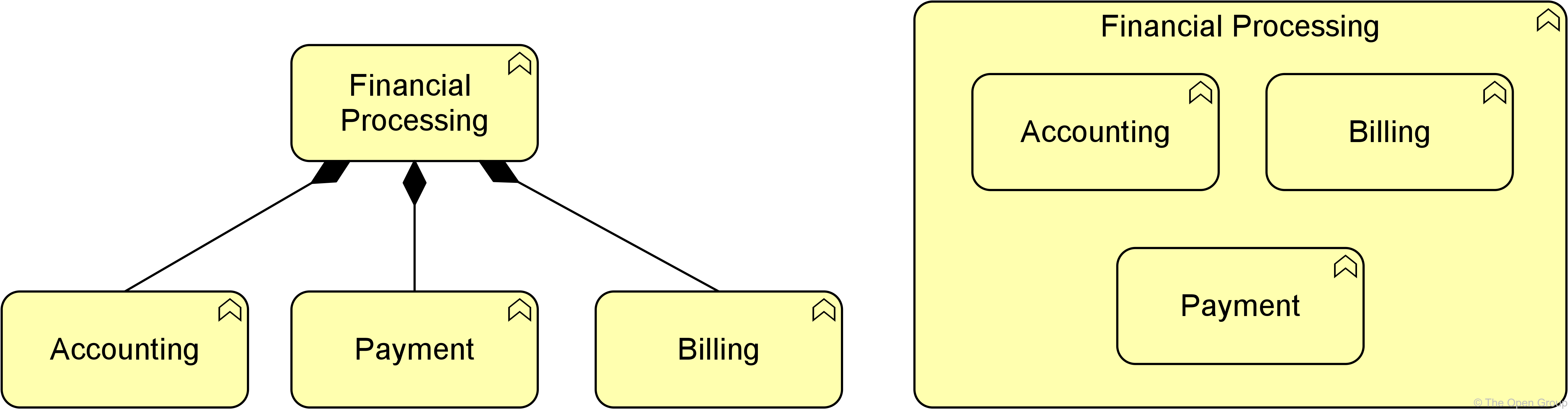
As an alternative to the graphical notations proposed in this section, structural relationships may also be expressed by nesting the united concept within the uniting element. Note, however, that this can lead to ambiguous views (although unambiguous in the model), in case multiple structural relationships are allowed between these elements.
5.1.1. Composition Relationship
The composition relationship represents that an element consists of one or more other concepts.
The composition relationship has been inspired by the composition relationship in UML class diagrams. Composition is a whole/part relationship that expresses an existence dependency: if a composite is deleted, its parts are (normally) deleted as well. When you model real-world elements – for example, an organization structure of departments and teams expressed as business actors – this dependency applies to these elements themselves. When you model exemplars or categories – as is common in Enterprise Architecture – this dependency may be interpreted as applying to their real-world instances. For example, a specific kind of server can be modeled as a node composed of a device and system software; this implies an existence dependency between individual servers of that kind and the individual devices and system software instances of which they consist.
A composition relationship is always allowed between two instances of the same element type.
In addition to this, the metamodel explicitly defines other source and target elements that may be connected by a composition relationship.

The interpretation of a composition relationship is that the whole or part of the source element is composed of the whole of the target element. See also Section 5.1.5.
Example
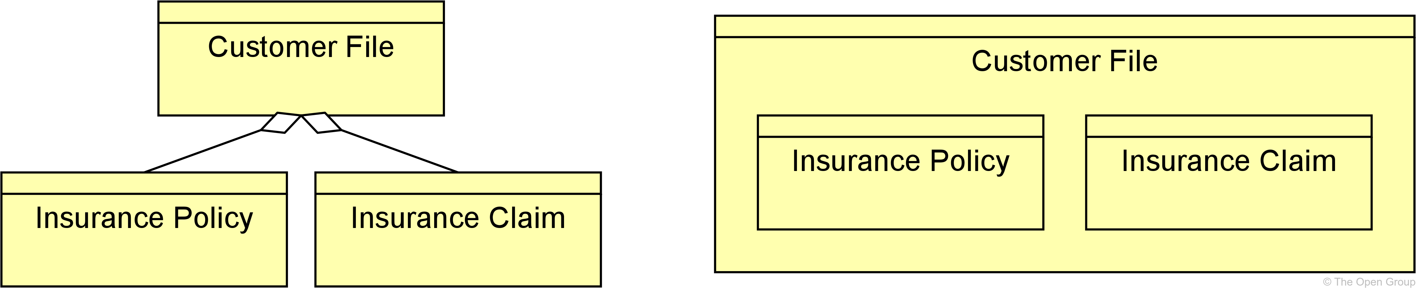
5.1.2. Aggregation Relationship
The aggregation relationship represents that an element combines one or more other concepts.
The aggregation relationship has been inspired by the aggregation relationship in UML class diagrams. Unlike composition, aggregation does not imply an existence dependency between the aggregating and aggregated concepts.
An aggregation relationship is always allowed between two instances of the same element type.
In addition to this, the metamodel explicitly defines other source and target elements that may be connected by an aggregation relationship.

The interpretation of an aggregation relationship is that the whole or part of the source element aggregates the whole of the target concept. See also Section 5.1.1.
Example
5.1.3. Assignment Relationship
The assignment relationship represents the allocation of responsibility, performance of behavior, storage, or execution.
The assignment relationship links active structure elements with units of behavior that are performed by them, business actors with business roles that are fulfilled by them, and nodes with technology passive structure elements. It can, for example, relate an internal active structure element with an internal behavior element, an interface with a service, or a node, device, and system software with an artifact. The full set of permitted relationships is listed in Appendix B.

In the ArchiMate framework described in Section 3.4, it always points from active structure to behavior, from behavior to passive structure, and from active to passive structure. The non-directional notation from the ArchiMate 2.1 Specification and before, which shows the black ball at both ends of the relationship, is still allowed but deprecated.
As with all structural relationships, an assignment relationship can also be expressed by nesting the model elements. The direction mentioned above is also the direction of nesting; for example, a business role inside the business actor performing that role, an application function inside an application component executing that function, or an artifact inside a node that stores it.
The interpretation of an assignment relationship is that the whole or part of the source element is assigned the whole of the target element (see also Section 5.1). This means that if, for example, two active structure elements are assigned to the same behavior element, either of them can perform the complete behavior. If both active structure elements are needed to perform the behavior, the grouping element or a junction (see Section 5.5) can be used, and if the combination of these elements has a more substantive and independent character, a collaboration would be the right way to express this.
Example
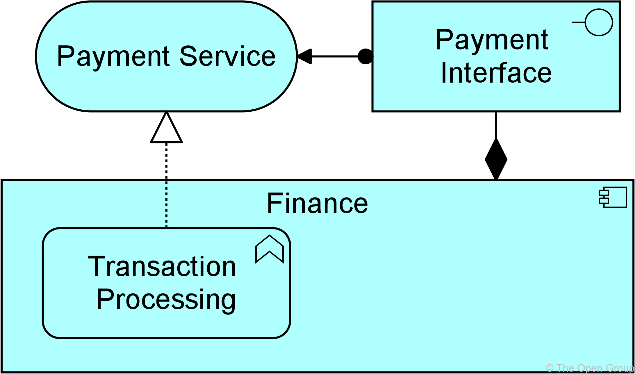
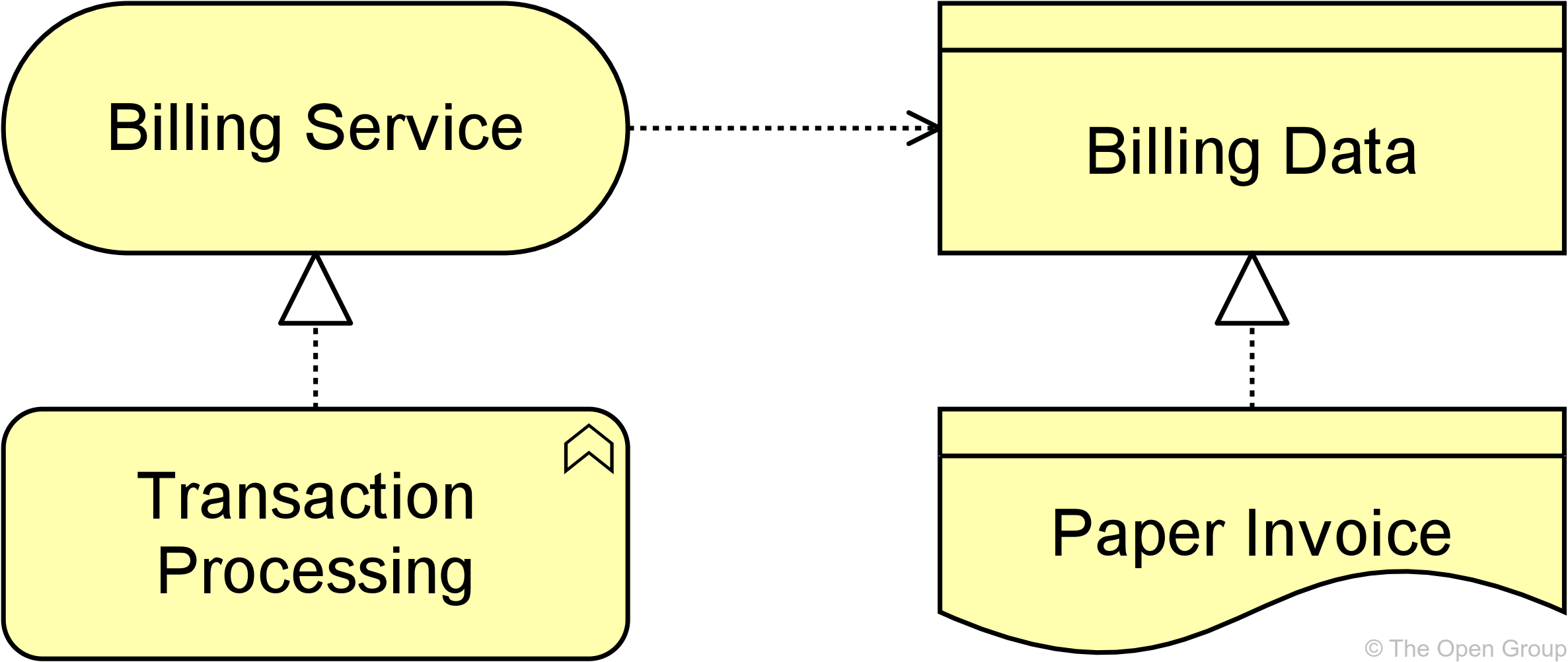
5.1.4. Realization Relationship
The realization relationship represents that an element plays a critical role in the creation, achievement, sustenance, or operation of a more abstract element.
The realization relationship indicates that more abstract elements (“what” or “logical”) are realized by means of more tangible elements (“how” or “physical”). The realization relationship is used to model run-time realization; for example, that a business process realizes a business service, and that a data object realizes a business object, an artifact realizes an application component, or a core element realizes a motivation element.

The interpretation of a realization relationship is that the whole or part of the source element realizes the whole of the target element (see also Section 5.1). This means that if, for example, two internal behavior elements have a realization relationship to the same service, either of them can realize the complete service. If both internal behavior elements are needed to realize, the grouping element or an and junction (see Section 5.5.1) can be used. For weaker types of effects on the realization of a motivation element, the influence relationship (see Section 5.2.3) should be used.
Example
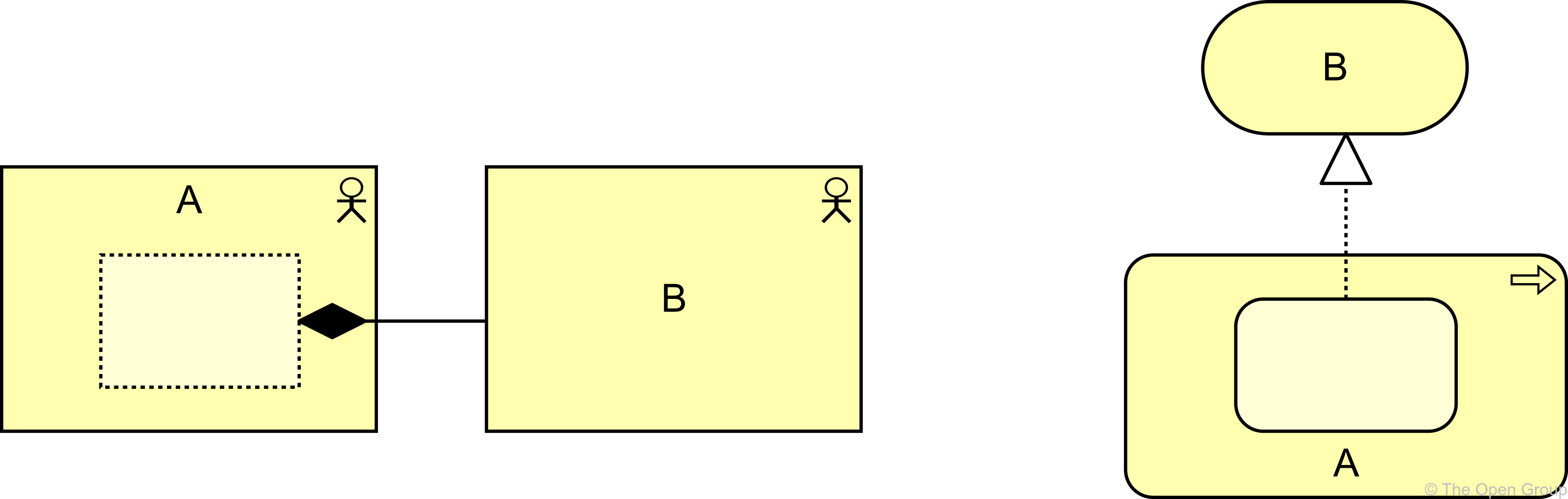
5.1.5. Semantics of Structural Relationships
Structural relationships describe that the element on the source side contains, groups, performs, or realizes the concept on the target side of the relationship. Structural relationships can be transitively applied to (possibly unmodeled) parts of the source element. Below are some examples of how these semantics work:
-
Composition and aggregation relationships from parts also apply to the whole
For example, if a part of A aggregates B, A itself is also considered to aggregate B. Conversely, if A aggregates B, that can be interpreted as some part of A aggregating B.
-
Assignment relationships to behavior elements also apply to the active structure elements
For example, if business role A is assigned to business process B, some part of A may perform B. Conversely, if a part of A is assigned to B, A itself is also considered to be assigned to B.
-
Realization relationships to external behavior elements also apply to the internal behavior elements
For example, if a service B is realized by a process A, B may be realized by some part of A. Conversely, if a part of A realizes B, A itself is also considered to realize B.
Example
5.2. Dependency Relationships
Dependency relationships describe how elements support or are used by other elements. Four types of dependency relationship are distinguished:
-
The serving relationship represents a control dependency, denoted by a solid line
-
The access relationship represents a data dependency, denoted by a dotted line
-
The influence relationship represents an impact dependency, denoted by a dashed line
-
The association relationship represents a dependency not covered by any of the other relationships
Note that, although the notation of these relationships resembles the notation of the dependency relationship in UML, these relationships have distinct meanings in ArchiMate notation and (usually) point in the opposite direction. One advantage of this is that it yields models with directionality, where most of the arrows that represent such supporting, influencing, serving, or realizing dependencies point “upwards” towards the client/user/business, as you can see in the layered viewpoint example in Section C.1.5. Another reason for this direction, in particular for the serving relationship, is that it abstracts from the “caller” or “initiator”, since a service may be delivered proactively or reactively. The direction of delivery is always the same, but the starting point for the interaction can be on either end. UML’s dependency is often used to denote the latter, showing that the caller depends on some operation that is called. However, for modeling this type of initiative, the ArchiMate language provides the triggering relationship (Section 5.3.1), which can be interpreted as a dynamic (i.e., temporal) dependency. Similarly, the flow relationship is used to model how something (usually information) is transferred from one element to another, which is also a dynamic kind of dependency.
5.2.1. Serving Relationship
The serving relationship represents that an element provides its functionality to another element.
The serving relationship describes how the services or interfaces offered by a behavior or active structure element serve entities in their environment. This relationship is applied for both the behavior aspect and the active structure aspect.
Compared to the earlier versions of this standard, the name of this relationship has been changed from “used by” to “serving”, to better reflect its direction with an active verb: a service serves a user. The meaning of the relationship has not been altered. The “used by” designation is still allowed but deprecated, and will be removed in a future version of the standard.

Example
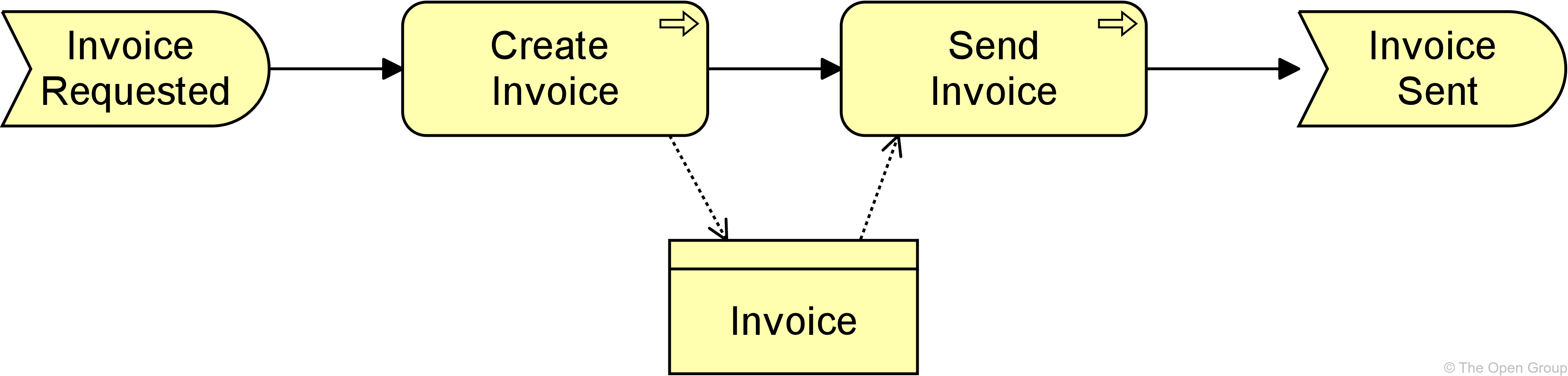
5.2.2. Access Relationship
The access relationship represents the ability of behavior and active structure elements to observe or act upon passive structure elements.
The access relationship indicates that a process, function, interaction, service, or event “does something” with a passive structure element; e.g., create a new object, read data from the object, write or modify the object data, or delete the object. The relationship can also be used to indicate that the object is just associated with the behavior; e.g., it models the information that comes with an event, or the information that is made available as part of a service. The arrowhead, if present, indicates the creation, change, or usage of passive structure elements. The access relationship should not be confused with the UML dependency relationship, which uses a similar notation.
Note that, at the metamodel level, the direction of the relationship is always from an active structure element or a behavior element to a passive structure element, although the notation may point in the other direction to denote “read” access, and in both directions to denote read-write access. Care must be taken when using access with derived relationships because the arrow on the relationship has no bearing to its directionality.

Alternatively, an access relationship can be expressed by nesting the passive structure element inside the behavior or active structure element that accesses it; for example, nesting a data object inside an application component.
Example
5.2.3. Influence Relationship
The influence relationship represents that an element affects the implementation or achievement of some motivation element.
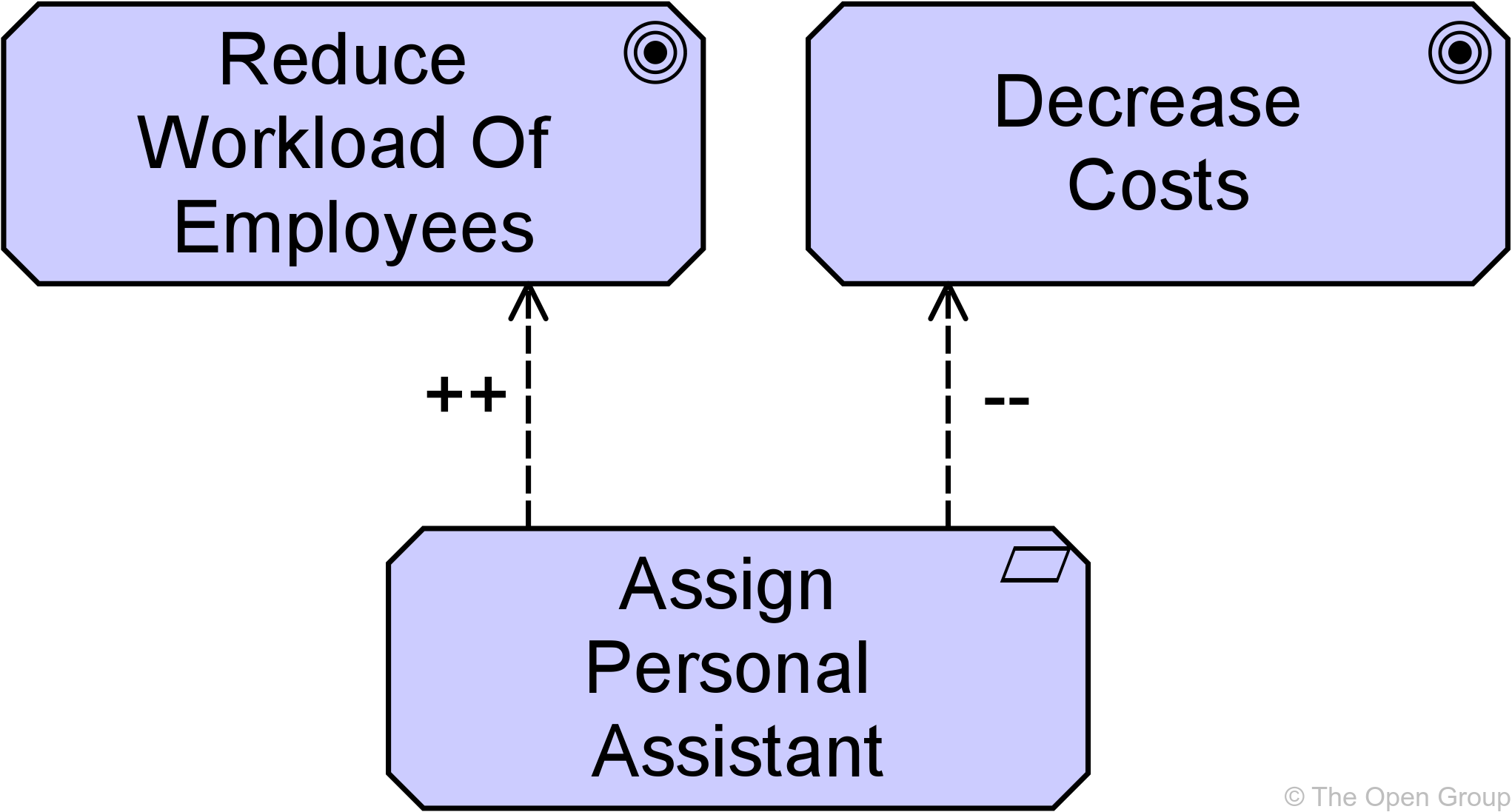
The influence relationship is used to describe some architectural elements that influence the achievement or implementation of a motivation element, such as a goal or a principle. In general, a motivation element is realized to a certain degree. For example, consistently satisfying the principle “serve customers wherever they are”, will help to make the goal “increase market share”, come true. In other words, the principle contributes to the goal. In turn, to implement the principle “serve customers wherever they are”, it may be useful to impose a requirement of “24x7 web availability” on some customer-facing application component. This can be modeled as a requirement that has an influence on that principle and as an application component that in turn influences the requirement. Consistently modeling these dependencies with an influence relationship yields a traceable motivational path that explains why, in this example, a certain application component contributes to the corporate goal to “increase market share”. This kind of traceability supports measuring the results of Enterprise Architecture and provides valuable information to, for example, change impact assessments.
Additional to this “vertical” use of contribution, from core elements upwards to requirements and goals, the relationship can also be used to model “horizontal” contributions between motivation elements. The influence relationship in that case describes that some motivation element may influence (the achievement or implementation of) another motivation element. In general, a motivation element is achieved to a certain degree. An influence by some other element may affect this depending on the degree in which the other element is satisfied itself. For example, the degree in which a goal to increase customer satisfaction is realized, may be represented by the percentage of satisfied customers that participate in a market interview. This percentage may be influenced by, for example, the goal to improve the reputation of the company; i.e., a higher degree of improvement results in a higher increase in customer satisfaction. On the other hand, the goal to lay off employees may influence the company reputation negatively; i.e., more lay-offs could result in a lower increase (or even decrease) in the company reputation. Thus (indirectly), the goal to increase customer satisfaction may also be influenced negatively.
The realization relationship should be used to represent relationships that are critical to the existence or realization of the target. The influence relationship should be used to represent relationships that are not critical to the target object’s existence or realization. For example, a business actor representing a construction crew may realize the goal of constructing a building, and a requirement to add additional skilled \ workers to an already adequate crew may influence the goal of constructing the building. However, the business actor also realizes an additional goal of opening the building by a particular date. An influence relationship can be used to model either:
-
The fact that an element positively contributes to the achievement or implementation of some motivation element, or
-
The fact that an element negatively influences – i.e., prevents or counteracts – such achievement
Attributes can be used to indicate the sign and/or strength of the influence. The choice of possible attribute values is left to the modeler; e.g., \{++, +, 0, -, --} or [0..10]. By default, the influence relationship models a contribution with unspecified sign and strength.

Example
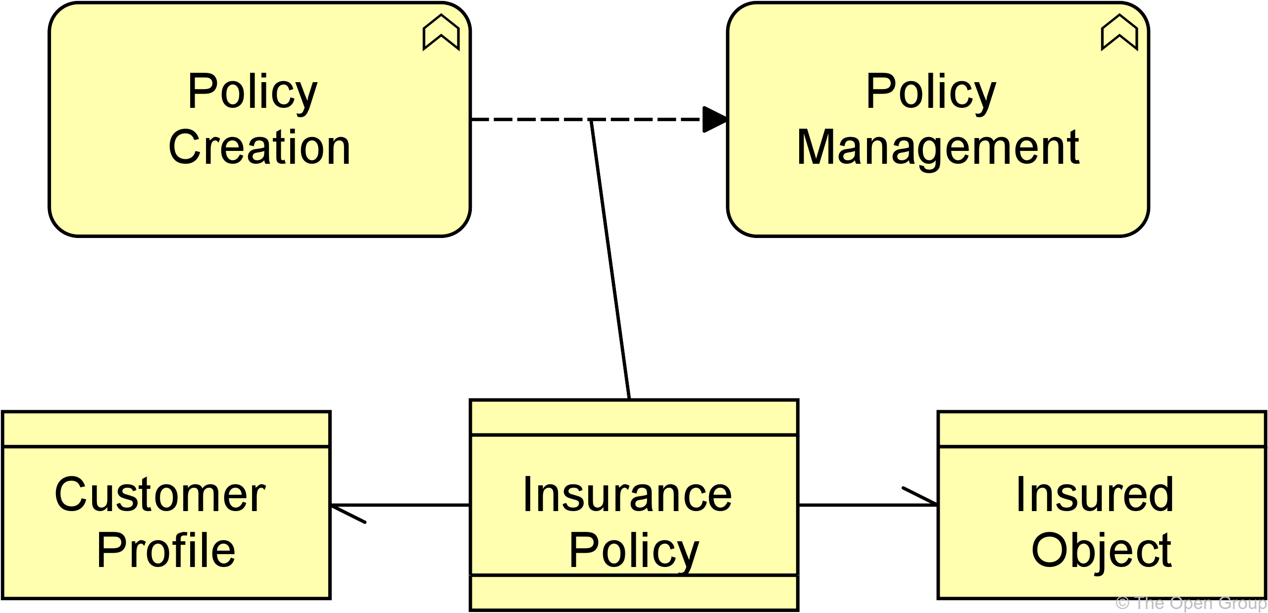
5.2.4. Association Relationship
An association relationship represents an unspecified relationship, or one that is not represented by another ArchiMate relationship.
An association relationship is always allowed between two elements, or between a relationship and an element.
The association relationship can be used when drawing a first high-level model where relationships are initially denoted in a generic way, and later refined to show more specific relationship types. In the metamodel pictures, some specific uses of the association relationship are explicitly shown. An association is undirected by default but may be directed. See also Section 5.2.5.
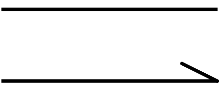
Example
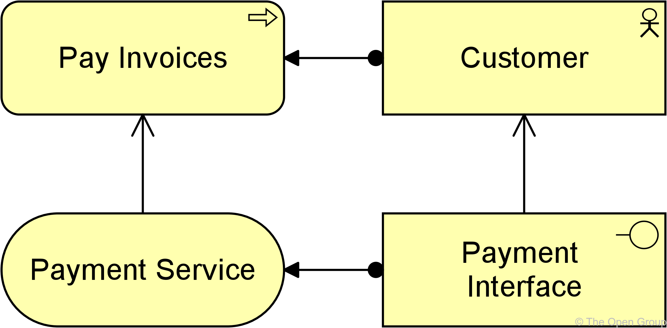
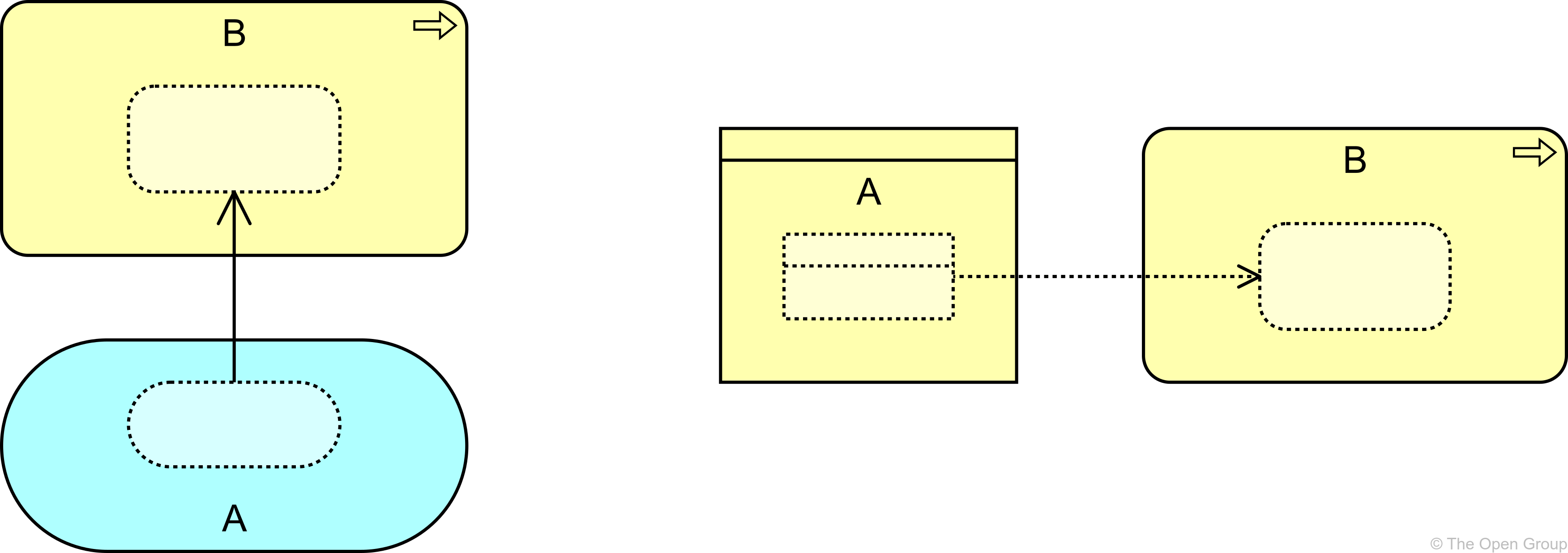
5.2.5. Semantics of Dependency Relationships
Dependency relationships describe that a part of the target element has a dependency on a part of the source element. Although there is a dependency between the two elements, it does not necessarily mean this applies to all of the parts of the element as defined by any structural relationships.
This semantic allows you to model dependencies at a high level (with details removed) without implying specific dependencies at a more detailed level. This means, for example, that:
-
In serving relationships, some part of an internal behavior element is served by some part of an external behavior element; for example, if a business service A serves a business process B, some unmodeled sub-service of A may serve an unmodeled sub-process of B
-
In access relationships, some part of a behavior element accesses some part of a passive structure element; for example, if an application function A accesses a data object B, some unmodeled sub-function of A may access an unmodeled part of B
-
In influence relationships, some part of a core element influences some part of a motivational element; for example, if an application component A influences a requirement B, some unmodeled part of A may influence some unmodeled part of B
-
In association relationships, some part of an element is related to some part of another element; if it is directed, it can only be used in derivations in that direction (see Section 5.7)
Example
5.3. Dynamic Relationships
The dynamic relationships describe temporal dependencies between elements within the architecture. Two types of dynamic relationships are distinguished: triggering and flow.
5.3.1. Triggering Relationship
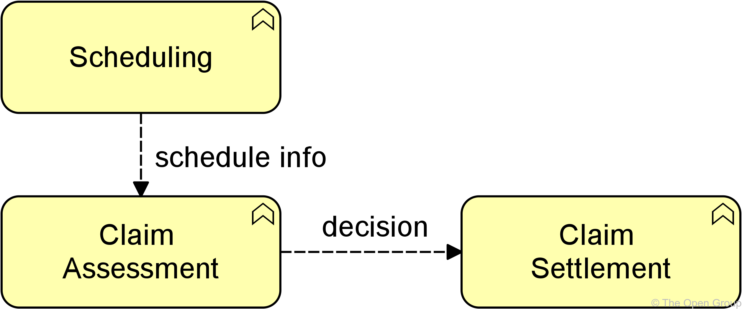
The triggering relationship represents a temporal or causal relationship between elements.
The triggering relationship is used to model the temporal or causal precedence of behavior elements in a process. The interpretation of a triggering relationship is that some part of the source element should be completed before the target element can start (see also Section 5.3.3). Note that this does not necessarily represent that one behavior element actively starts another; a traffic light turning green also triggers the cars to go through the intersection.

Example
5.3.2. Flow Relationship
The flow relationship represents transfer from one element to another.
The flow relationship is used to model the flow of, for example, information, goods, or money between behavior elements. A flow relationship does not imply a causal relationship.

Example
5.3.3. Semantics of Dynamic Relationships
The semantics of triggering and flow relationships differ. The triggering relationship follows the same semantics as structural relationships (Section 5.1.5). A triggering relationship from A to B indicates that everything in B is preceded by a part of A. When A and B are business processes, for example, it means that all steps in business process B are performed after a part of A has occurred, but steps in A can occur after some or all steps in B have occurred. A stronger interpretation of triggering (everything in B is preceded by everything in A) could be imposed on the ArchiMate model by a modeling group wishing to do so.
The flow relationships follow the same semantics as dependency relationships (see Section 5.2.5). A flow relationship from A to B indicates that the whole or some part of A transfers something (e.g., information) to the whole or some part of B.
5.4. Other Relationships
5.4.1. Specialization Relationship
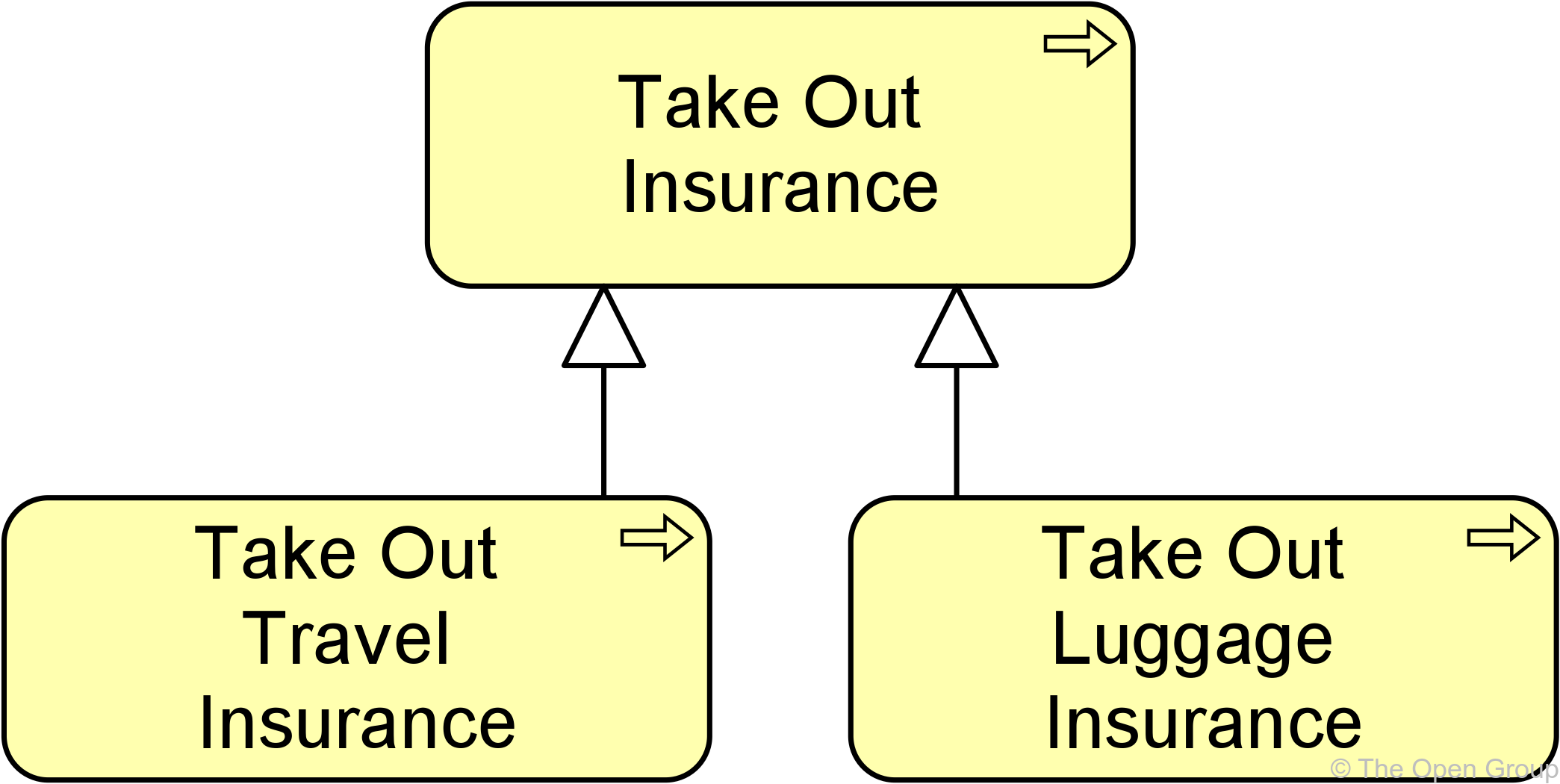
The specialization relationship represents that an element is a particular kind of another element.
The specialization relationship has been inspired by the generalization relationship in UML class diagrams but is applicable to specialize a wider range of concepts.
A specialization relationship is always allowed between two instances of the same element type.

Alternatively, a specialization relationship can be expressed by nesting the specialized element inside the generic element.
Example
5.4.2. Semantics of Other Relationships
The semantics of the specialization relationship are that the whole of the generic element is specialized by the specialized element.
5.5. Relationship Connectors
5.5.1. Junction
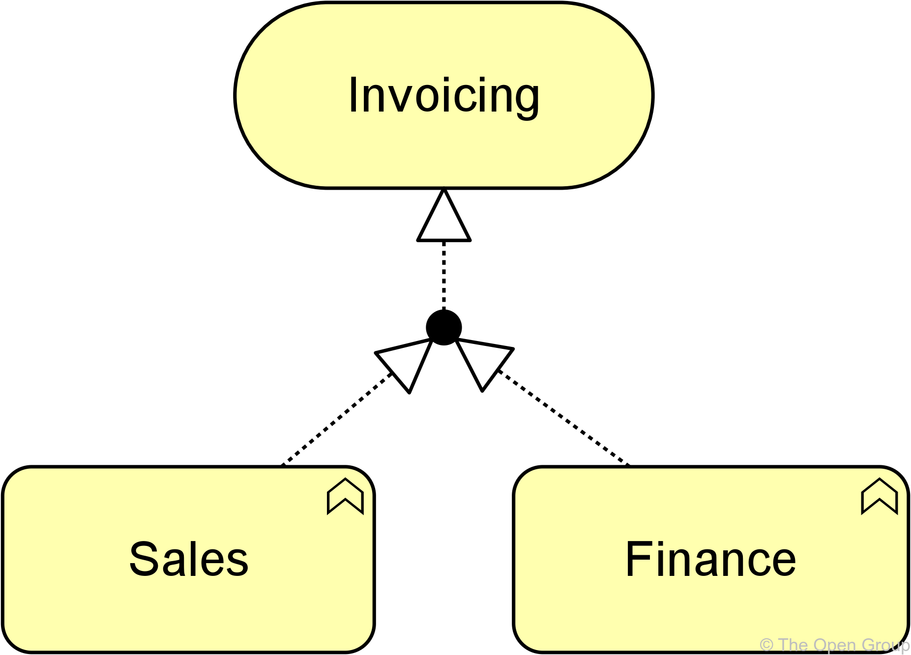
A junction is not an actual relationship in the same sense as the other relationships described in this chapter, but rather a relationship connector.
A junction is used to connect relationships of the same type.
A path with junctions that connect relationships of a specific type is only allowed between two concepts if a direct relationship of that type between these concepts is also permitted. Simply put, you cannot use junctions to create relationships between concepts that would otherwise not be allowed.
A junction may have multiple incoming relationships and one outgoing relationship, one incoming relationship and multiple outgoing relationships, or multiple incoming and outgoing relationships (the latter can be considered a shorthand of two contiguous junctions).
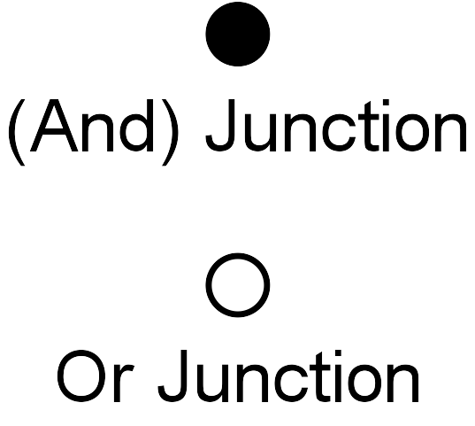
A junction is used to explicitly express that all elements together must participate in the relationship (and junction) or that at least one of the elements participates in the relationship (or junction). The or junction can be used to express both inclusive and exclusive or conditions, which could be indicated by a modeler by naming the junction to reflect its type.
In addition to the above, a junction (which connects some relationships), may also be aggregated or composed in a plateau, grouping, or location element. If that junction connects other aggregation or composition relationships, it should be interpreted without the aggregation or composition to this containing element. The composition or aggregation merely states that the junction is part of a plateau, grouping, or location. Without that relationship, the junction must fulfill the same conditions as above: it connects relationships of the same type, with at least one incoming and one outgoing relationship.
It is allowed to omit arrowheads of relationships leading into a junction.

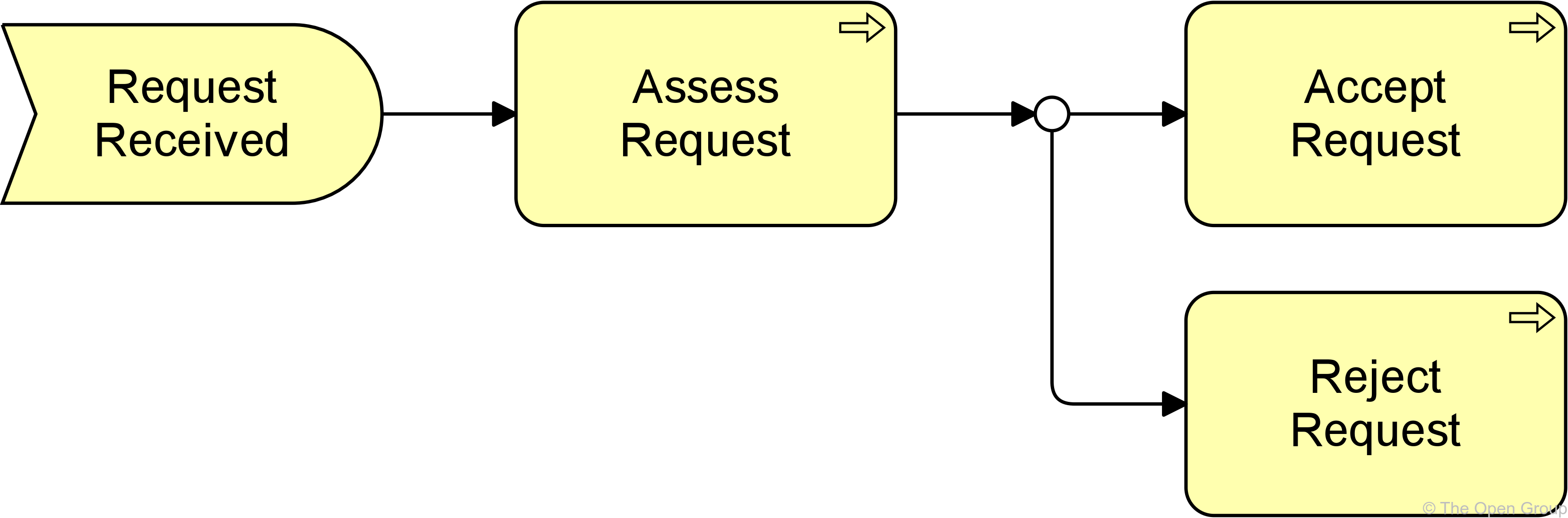
Junctions may be used on triggering relationships. This is a technique used by other modeling languages. For example, the BPMN notation uses gateways as junctions, and the UML notation uses forks and joins in their modeling activity diagrams. They can be used to model high-level process flow. A label may be added to outgoing triggering relationships of a junction to indicate a choice, condition, or guard that applies to that relationship. Such a label is only an informal indication. No formal, operational semantics have been defined for these relationships because implementation-level languages such as BPMN and UML, differ in their execution semantics and the ArchiMate language does not want to unduly constrain mappings to such languages.
Examples
5.6. Summary of Relationships
Table 3 gives an overview of the ArchiMate relationships with their definitions.
| Structural Relationships | Notation | Role Names | |
|---|---|---|---|
Composition |
Represents that an element consists of one or more other concepts. |
|
→ composed of |
Aggregation |
Represents that an element combines one or more other concepts. |
|
→
aggregates |
Assignment |
Represents the allocation of responsibility, performance of behavior, storage, or execution. |
|
→ assigned to |
Realization |
Represents that an element plays a critical role in the creation, achievement, sustenance, or operation of a more abstract element. |
|
→ realizes |
Dependency Relationships |
Notation |
Role Names |
|
Serving |
Represents that an element provides its functionality to another element. |
|
→
serves |
Access |
Represents the ability of behavior and active structure elements to observe or act upon passive structure elements. |
|
→ accesses |
Influence |
Represents that an element affects the implementation or achievement of some motivation element. |
|
→ influences |
Association |
Represents an unspecified relationship, or one that is not represented by another ArchiMate relationship. |
|
associated with |
Dynamic Relationships |
Notation |
Role Names |
|
Triggering |
Represents a temporal or causal relationship between elements. |
|
→ triggers |
Flow |
Represents transfer from one element to another. |
|
→ flows to |
Other Relationships |
Notation |
Role Names |
|
Specialization |
Represents that an element is a particular kind of another element. |
|
→
specializes |
Relationship Connectors |
Notation |
Role Names |
|
Junction |
Used to connect relationships of the same type. |
|
5.7. Derivation of Relationships
In the ArchiMate language, you can derive indirect relationships between elements in a model, based on the modeled relationships. This makes it possible to abstract from intermediary elements that are not relevant in order to show a certain model or view of the architecture that supports impact analysis. The precise rules for making such derivations are specified in Appendix B.
Example
Derivation of relationships is intended as a way to create summaries of detailed models. It is a way to remove (to abstract from) details in a model while still making valid “statements”. Hence, derivation is always meant to go from more detail to less detail. This mechanism is one of the unique properties of the ArchiMate language compared to other modeling languages.
The language allows the modeler to directly create relationships that are necessarily valid derived relationships without the constituents of the derivation being available in the model. These relationships (for example, a realization relationship between an application component and an application service) assume that the required constituents (for example, an application function) needed for the derived relationship exist; however, these missing elements need not be modeled explicitly, and the derived relationships can be used as if they have not been derived. Thus, the modeler has full freedom in choosing the required level of detail.
Because the essence of derivation is to make simplifications or summaries, it cannot be used to infer more detail. For example, a realization relationship from an application component to an application service can be modeled, but from it no conclusions can be drawn about the exact source of this derivation (e.g., which functions realize which services).
This is information that should be added by a modeler during the design process: a higher-level, more abstract model can be refined by elaborating the derived relationships (in the previous example by adding an application function that realizes the application service and to which the application component is assigned).
It is important to note that all these derived relationships are also valid in the ArchiMate language. They are not shown in the metamodel diagrams included in the standard because this would reduce their legibility. However, the tables in Appendix B show all permitted relationships between two elements in the language.