10. Technology Layer
The Technology Layer elements are typically used to model the Technology Architecture of the enterprise, describing the structure and behavior of the technology infrastructure of the enterprise.
The physical elements are an extension to the Technology Layer for modeling the physical world. They only include active and passive structure elements; no specific physical behavior elements are defined. Physical technology elements can be combined with other technology elements (such as device) and be part of the same node, to model an integrated piece of operational and information technology.
10.1. Technology Layer Metamodel
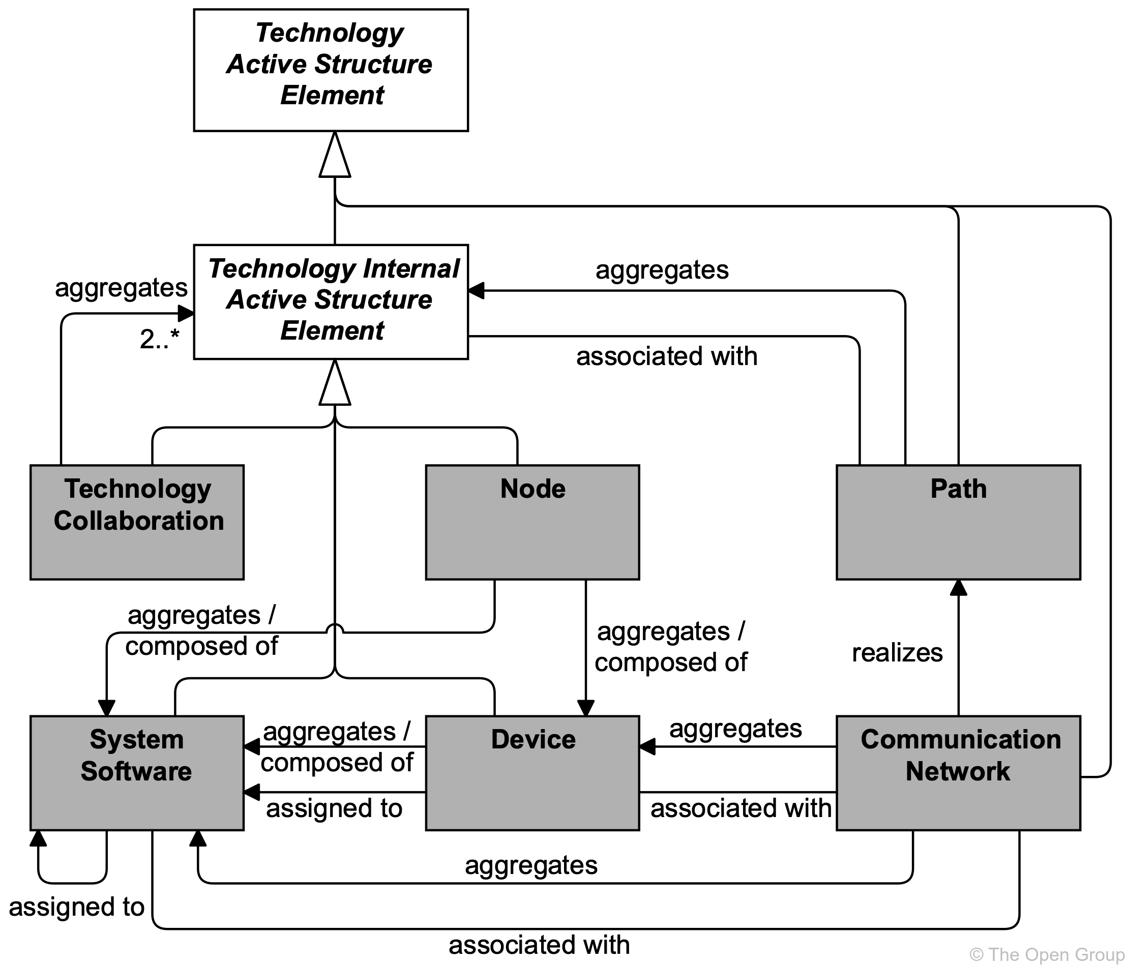
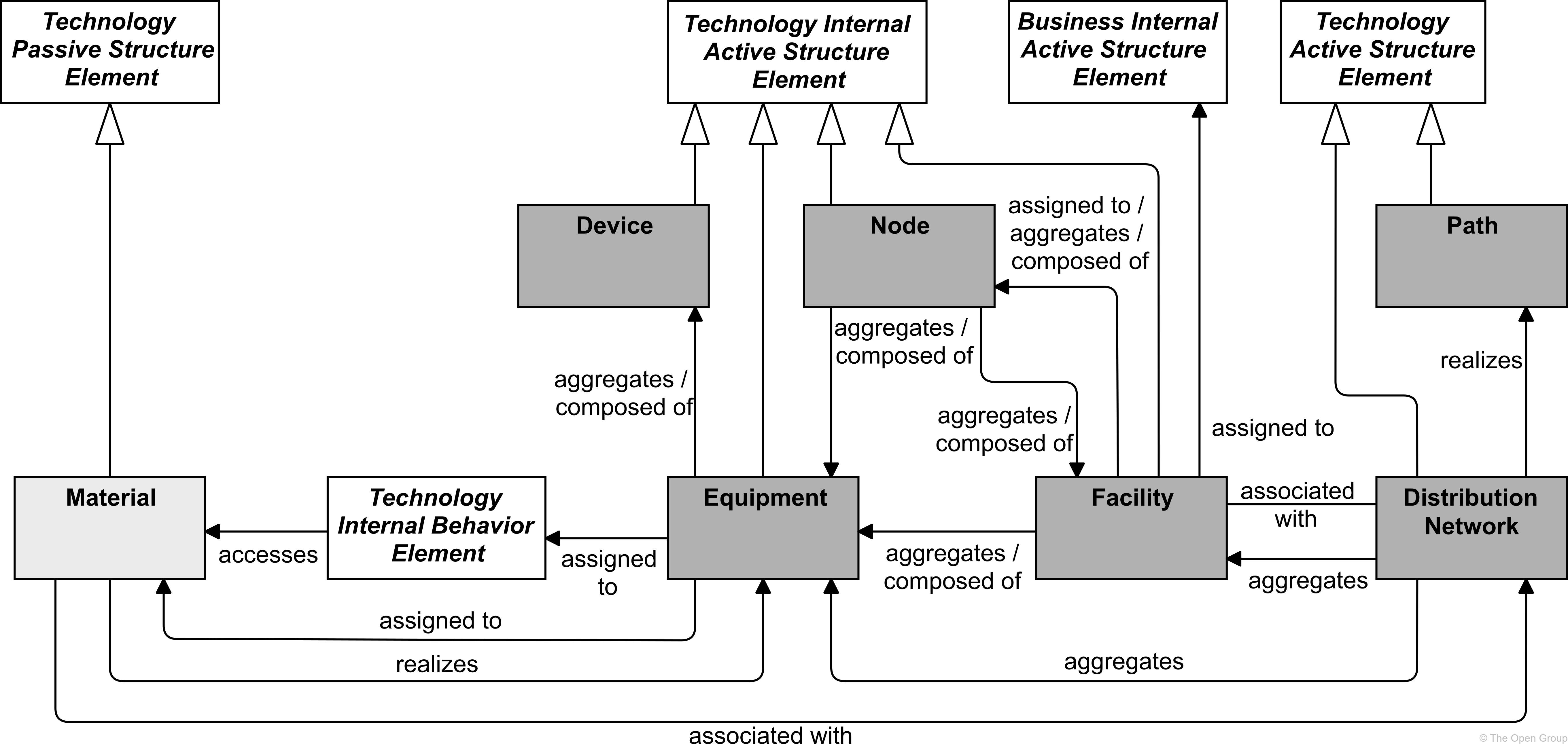
Figure 82 gives an overview of the Technology Layer elements and their relationships. Whenever applicable, inspiration is drawn from the analogy with the Business and Application Layers. In the following sections, several more elements will be introduced.
|
Note
|
This figure does not show all permitted relationships; every element in the language can have composition, aggregation, and specialization relationships with elements of the same type. Furthermore, there are indirect relationships that can be derived, as explained in Section 5.7. |
10.2. Active Structure Elements
The main active structure element for the Technology Layer is the node. This element is used to model structural entities in this layer. It strictly models the structural aspect of a system: its behavior is modeled by an explicit relationship to a behavior element.
A technology interface is the (logical) place where the technology services offered by a node can be accessed by other nodes or by application components from the Application Layer.
Nodes can consist of information and technology elements modeled as devices and system software, and also of physical technology elements modeled as facilities and equipment (see Section 10.6). A device models a physical computational resource, upon which artifacts may be deployed for execution. System software is an infrastructural software component running on a device. Typically, a node consists of a number of sub-nodes; for example, a device such as a server and system software to model the operating system.
The inter-relationships of components in the Technology Layer are mainly formed by the communication infrastructure. The path models the relation between two or more technology internal active structure elements, through which these can exchange information. The physical realization of a path is modeled with a communication network; i.e., a physical communication medium between two or more devices (or other networks).
|
Note
|
This figure does not show all permitted relationships; every element in the language can have composition, aggregation, and specialization relationships with elements of the same type. Furthermore, there are indirect relationships that can be derived, as explained in Section 5.7. |
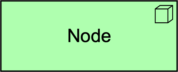
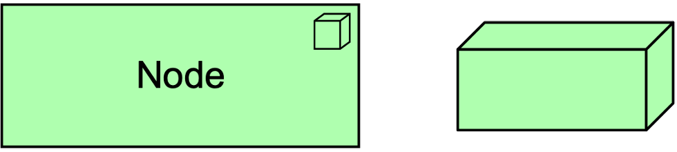
10.2.1. Node
A node represents a computational or physical resource that hosts, manipulates, or interacts with other computational or physical resources.
Nodes are active structure elements that perform technology behavior and execute, store, and process artifacts or materials. For instance, nodes are used to model application platforms, defined by the TOGAF framework [4] as: “a collection of technology components of hardware and software that provide the services used to support applications”.
Nodes can be interconnected by paths and may be assigned to an artifact to model that the artifact is deployed on the node.
The name of a node should preferably be a noun. A node may consist of sub-nodes.
Artifacts deployed on a node may either be drawn inside the node or connected to it with an assignment relationship.
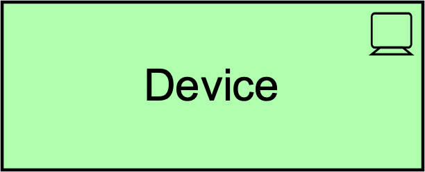
10.2.2. Device
A device represents a physical IT resource upon which system software and artifacts may be stored or deployed for execution.
A device represents a physical IT resource with processing capability. It is typically used to model hardware systems such as mainframes, PCs, smartphones, or routers. It can also be used to model virtualized hardware, e.g., in an IaaS environment. Usually, devices are part of a node together with system software. Devices may be composite; i.e., consist of sub-devices.
Devices can be interconnected by communication networks as well as being assigned to artifacts and to system software, to model deployment on that device. A node can contain one or more devices.
The name of a device should preferably be a noun phrase referring to the type of hardware; e.g., “IBM System z mainframe”.

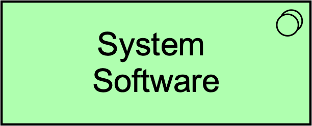
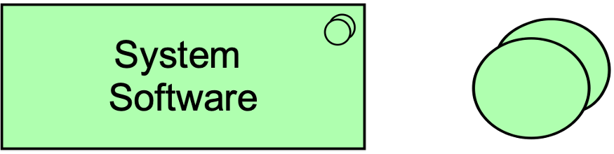
10.2.3. System Software
System software represents software that provides or contributes to an environment for storing, executing, and using software or data deployed within it.
System software is used to model the software environment in which artifacts run. This can be, an operating system, a JEE application server, a database system, or a workflow engine. System software can also be used to represent communication middleware. Usually, system software is combined with a device representing the hardware environment to form a general node.
A device or system software can be assigned to other system software; e.g., to model different layers of software running on top of each other. System software can be assigned to artifacts to model that these artifacts are deployed on that software and can realize other system software. A node can be composed of or aggregate system software.
The name of system software should preferably be a noun referring to the type of execution environment; e.g., “JEE server”. System software may be composed of other system software; e.g., an operating system containing a database.
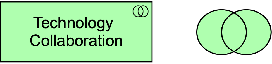
10.2.4. Technology Collaboration
A technology collaboration represents an aggregate of two or more technology internal active structure elements that work together to perform collective technology behavior.
A technology collaboration specifies which technology internal active structure elements and/or other technology collaborations cooperate to perform some task. The collaborative behavior, including the communication pattern of these elements, is modeled by a technology interaction. A technology collaboration typically models a logical or temporary collaboration of technology internal active structure elements and does not exist as a separate entity in the enterprise.
Technology collaboration is a specialization of technology internal active structure element, and aggregates two or more (cooperating) technology internal active structure elements. A technology collaboration is an internal active structure element that may be assigned to one or more technology interactions, or to other technology internal behavior elements that model the associated behavior. A technology interface may serve a technology collaboration, and a technology collaboration may be composed of technology interfaces. The name of a technology collaboration should preferably be a noun.
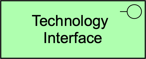
10.2.5. Technology Interface
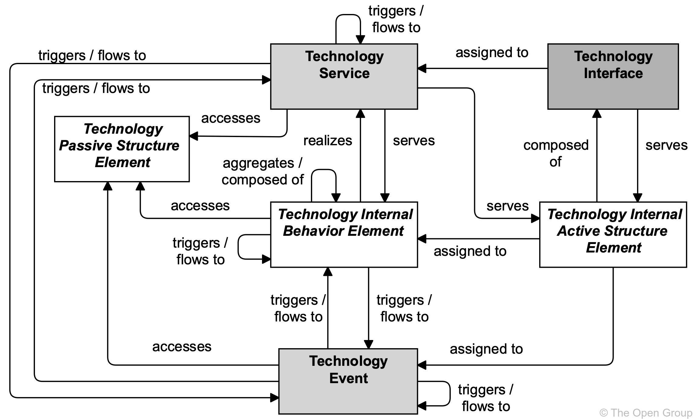
A technology interface represents a point of access where technology services offered by a technology internal active structure element can be accessed.
A technology interface specifies how the technology services of a technology internal active structure element can be accessed by other elements. A technology interface exposes a technology service to the environment. The same service may be exposed through different interfaces.
In a sense, a technology interface specifies a kind of contract that a node realizing this interface must fulfill. This may include, parameters, protocols used, pre- and post-conditions, and data formats.
A technology interface may be part of a technology internal active structure through composition, which means that these interfaces are provided by that element and can serve other elements. A technology interface can be assigned to a technology service, to expose that service to the environment.
The name of a technology interface should preferably be a noun.

|
Note
|
In previous versions of this standard, this element was called “infrastructure interface”. This usage is still permitted but deprecated and will be removed from a future version of the standard. |
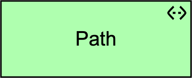
10.2.6. Path
A path represents a link between two or more technology internal active structure elements, through which these elements can exchange data, energy, or material.
A path is used to model the logical communication (or distribution) relations between technology internal active structure elements. It is realized by one or more communication networks (or distribution networks when modeling physical elements; see Section 10.6.3), which represent the physical communication (or distribution) links. The properties (e.g., bandwidth, latency) of a path are usually aggregated from these underlying networks.
A path connects two or more technology internal active structure elements. A path is realized by one or more networks. A path can aggregate nodes.

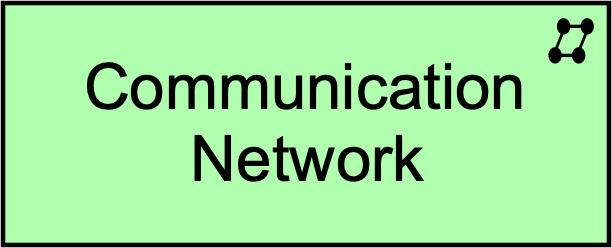
10.2.7. Communication Network
A communication network represents a set of structures that connects devices or system software for transmission, routing, and reception of data.
A communication network represents the physical communication infrastructure. It “provides the basic services to interconnect systems and provide the basic mechanisms for opaque transfer of data. It contains the hardware and software elements which make up the networking and physical communications links used by a system, and of course all the other systems connected to the network”, as described by the TOGAF Series Guide: The TOGAF Technical Reference Model (TRM) [19].
A communication network connects two or more devices or system software. The most basic communication network is a single link between two devices, but it may comprise multiple links and associated network equipment or software. A network has properties such as bandwidth and latency. A communication network realizes one or more paths. It embodies the physical realization of the logical path between nodes.
A communication network can consist of sub-networks. It can aggregate devices and system software to model the routers, switches, and firewalls that are part of the network infrastructure.

|
Note
|
Formerly, this element was called “network”. This usage is still permitted but deprecated and will be removed from a future version of the standard. |
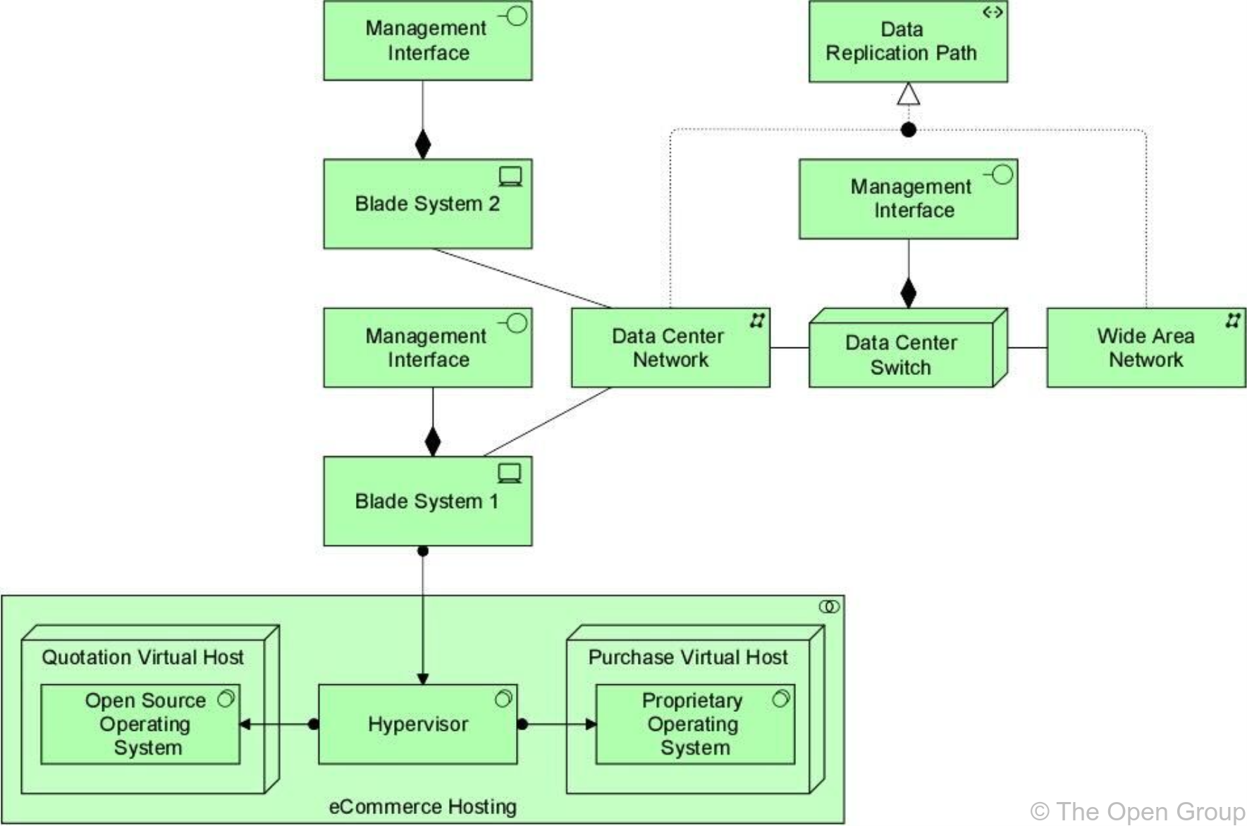
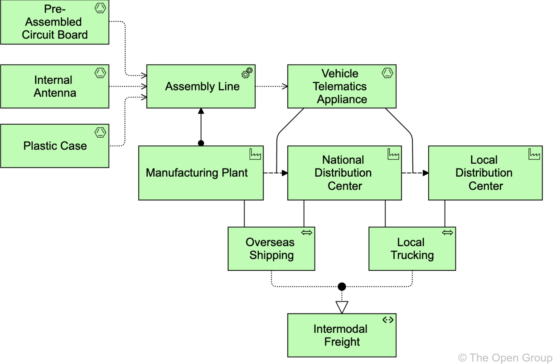
10.2.8. Example
10.3. Behavior Elements
Behavior elements in the Technology Layer are similar to the behavior elements in the other layers. As in the Business and Application Layers, a distinction is made between the external behavior of technology internal active structure elements in terms of technology services, and the internal behavior of these elements; i.e., technology functions, technology processes, and technology interactions that realize these services.
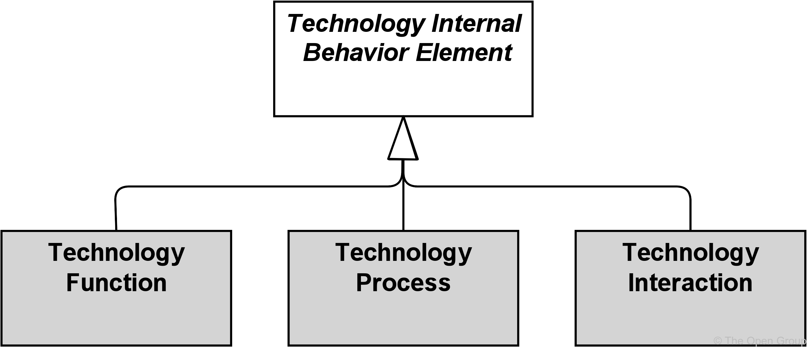
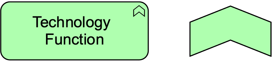
10.3.1. Technology Function
A technology function represents a collection of technology behavior that can be performed by a technology internal active structure element.
A technology function describes the internal behavior of a technology internal active structure element; for the user of an element that performs a technology function, this function is invisible. If its behavior is exposed externally, this is done through one or more technology services. A technology function abstracts from the way it is implemented. Only the necessary behavior is specified.
A technology function may realize technology services. A technology function may access technology passive structure elements. An internal active structure element may be assigned to a technology function (which means that the node performs the technology function). The name of a technology function should preferably be a verb ending with “-ing”.
|
Note
|
In previous versions of this standard, this element was called “infrastructure function”. This usage is still permitted but deprecated and will be removed from a future version of the standard. |
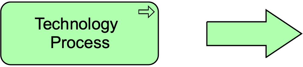
10.3.2. Technology Process
A technology process represents a sequence of technology behaviors that achieves a specific result.
A technology process describes internal behavior of a technology internal active structure element; for the user of that element, this process is invisible. If its behavior is exposed externally, this is done through one or more technology services. A technology process abstracts from the way it is implemented. Only the necessary behavior is specified. It can access technology passive structure elements as input and use or transform these to produce other technology passive structure elements as output.
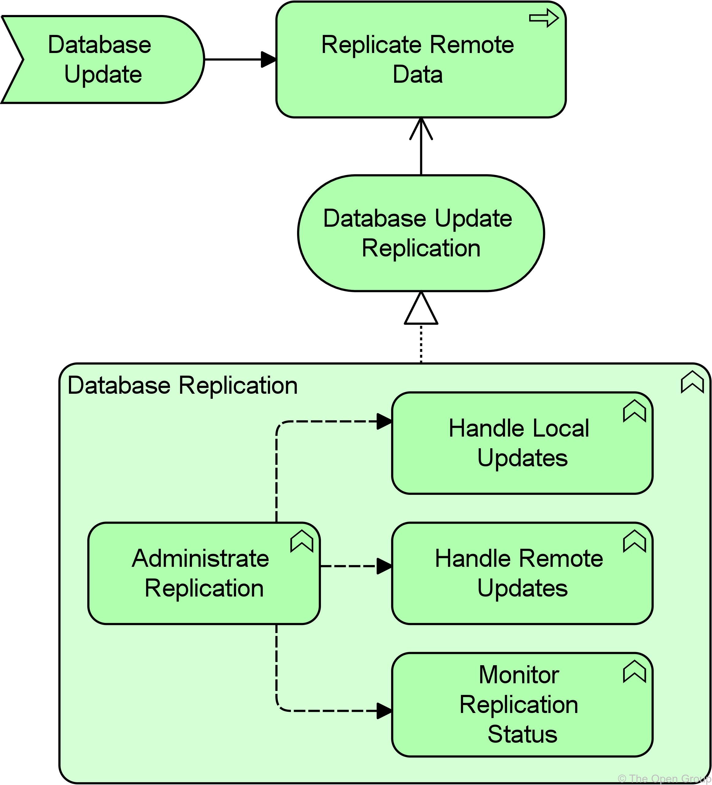
A technology process may realize technology services and other technology services may serve (be used by) a technology process. A technology internal active structure element may be assigned to a technology process, which means that this element performs the process. The name of a technology process should clearly identify a series of technology behaviors using a verb or verb-noun combination; e.g., “Boot up system” or “Replicate database”.
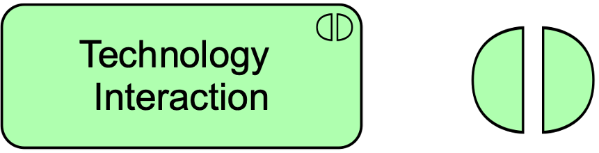
10.3.3. Technology Interaction
A technology interaction represents a unit of collective technology behavior performed by (a collaboration of) two or more technology internal active structure elements.
A technology interaction describes the collective behavior that is performed by two or more technology internal active structure elements, possibly via their participation in a technology collaboration. This may include the communication pattern between these elements. A technology interaction can also specify the joint behavior needed to realize a technology service. The details of the interaction between the technology internal active structure elements involved in a technology interaction, can be expressed during the detailed design using a UML interaction diagram.
A technology collaboration, or two or more nodes, may be assigned to a technology interaction. A technology interaction may realize technology services and technology services may serve a technology interaction. A technology interaction may access artifacts. The name of a technology interaction should clearly identify a collective technology behavior; e.g., “client profile creation” or “update customer records”.
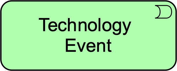
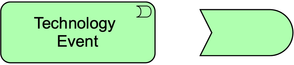
10.3.4. Technology Event
A technology event represents a technology state change.
Technology functions and other technology behavior may be triggered or interrupted by a technology event. Technology functions may raise events that trigger other technology behavior. Unlike processes, functions, and interactions, an event is instantaneous: it does not have a duration. Events may originate from the environment of the organization, but also internal events may occur generated by other devices within the organization.
A technology event may have a time attribute that denotes the moment or moments at which the event happens. For example, this can be used to model time schedules; e.g., to model an event that triggers a recurring infrastructure function such as making a daily backup.
A technology event may trigger or be triggered (raised) by a technology function, process, or interaction. A technology event may access an artifact or material and may be composed of other technology events. The name of a technology event should preferably be a verb in the perfect tense; e.g., “message received”.
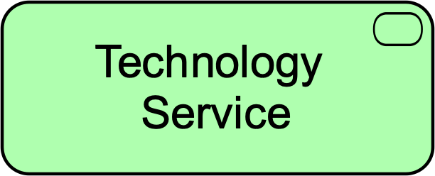
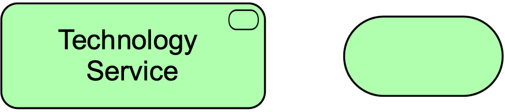
10.3.5. Technology Service
A technology service represents an explicitly defined exposed technology behavior.
A technology service exposes the functionality of a technology internal active structure element to its environment. This functionality is accessed through one or more technology interface and may require, use, and produce artifacts.
A technology service should be meaningful from the point of view of the environment; it should provide a unit of behavior that is, in itself, useful to its users, such as application components and nodes. This added value can be modeled as a value element associated with the service.
Typical technology services may include messaging, storage, naming, and directory services. It may access artifacts; e.g., a file containing a message.
A technology service may serve business, application components, and technology behavior or active structure elements . A technology service is realized by a technology function, process, or interaction. A technology service is exposed by a technology internal active structure element by assigning technology interfaces to it. A technology service may access artifacts. A technology service may consist of sub-services.
The name of a technology service should preferably be a verb ending with “-ing”; e.g., “messaging”. Also, a name explicitly containing the word “service” may be used.
|
Note
|
In previous versions of this standard, this element was called “infrastructure service”. This usage is still permitted but deprecated and will be removed from a future version of the standard. |
10.3.6. Example
10.4. Passive Structure Elements
Technology passive structure elements model the passive structure elements that are used and processed by the infrastructure. Technology passive structure elements represent the informational and physical objects manipulated by the infrastructure of an enterprise. They are abstract elements; i.e., they are not instantiated in models but serve as the generic type of the things manipulated by the Technology Layer. This may include both artifacts (e.g., files) and physical material.
Technology passive structure elements may be accessed by technology behavior (functions, processes, interactions, events, and services). A technology passive structure elements may have association, specialization, aggregation, or composition relationships with other technology passive structure elements. It may be an artifact (see Section 10.4.1) or material (see Section 10.7.1). Specific technology internal active structure elements may be assigned to technology passive structure elements. For example, a device may be assigned to an artifact, modeling the deployment of the artifact on that device.
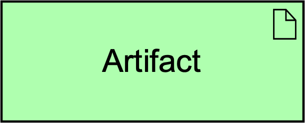
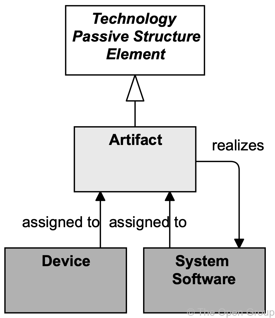
10.4.1. Artifact
An artifact represents a piece of data that is used or produced in a software development process, or by deployment and operation of an IT system.
An artifact represents a “physical” element in the IT world. Artifact is a specialization of technology passive structure elements. It is typically used to model (software) products such as source files, executables, scripts, database tables, messages, documents, specifications, and model files. It can be accessed (created, deleted, read, written) by technology behavior elements. An instance (copy) of an artifact can be deployed on a device or system software; this is modeled with an assignment relationship. An artifact could be used to represent a physical data component that realizes a data object.
An application component or system software may be realized by one or more artifacts. A data object may be realized by one or more artifacts. A device or system software element may be assigned to an artifact to model that the artifact is deployed on this element. Thus, the two typical ways to use the artifact element are as an execution component or as a data file. In fact, these could be defined as specializations of the artifact element.
The name of an artifact should preferably be the name of the file it represents; e.g., “order.jar”. An artifact may consist of sub-artifacts.
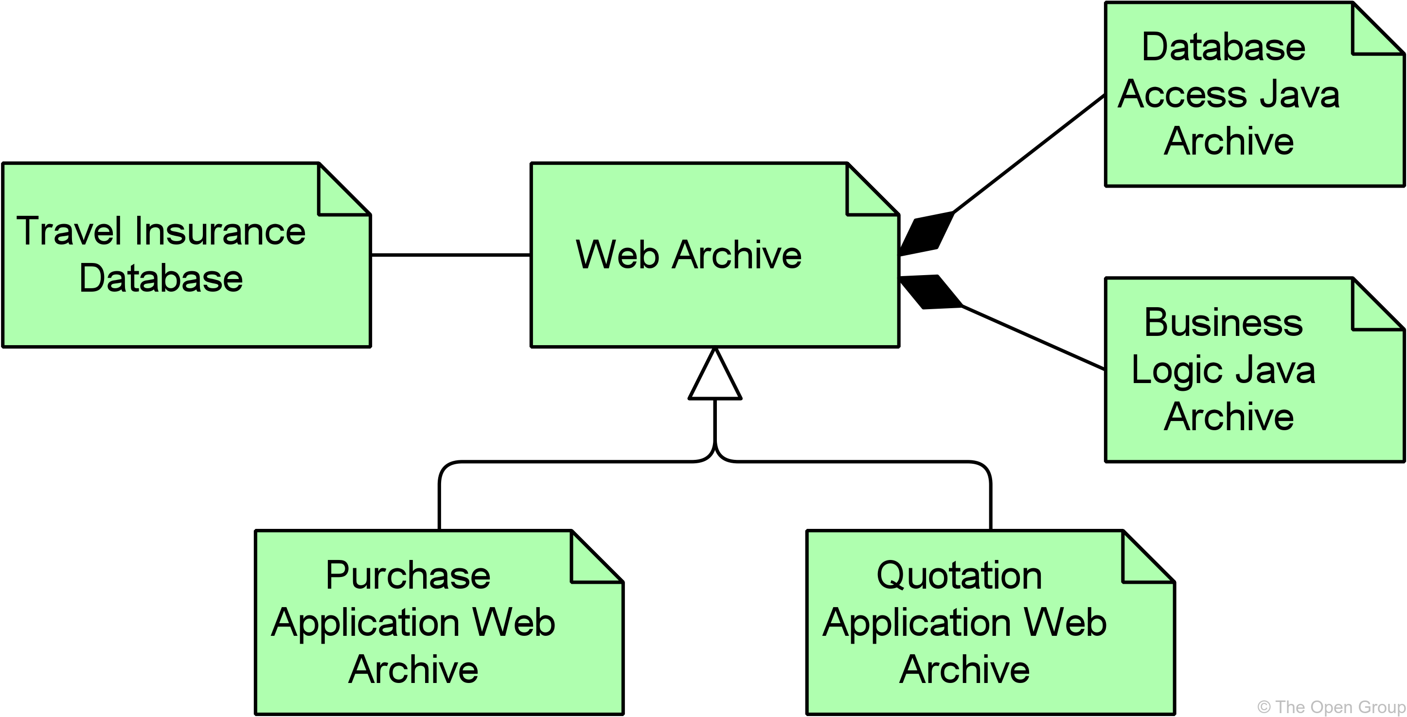
10.4.2. Example
10.5. Physical Elements Metamodel
Figure 99 gives an overview of the physical elements and their relationships.
|
Note
|
This figure does not show all permitted relationships; every element in the language can have composition, aggregation, and specialization relationships with elements of the same type. Furthermore, there are indirect relationships that can be derived, as explained in Section 5.7. |
10.6. Physical Active Structure Elements
The equipment element is the main active structure element within the physical elements. This element is used to model structural entities in this layer. It is used to model any physical machinery, tools, instruments, or implements. It strictly models the structural aspect of a system; its behavior is modeled by an explicit relationship to the behavior elements. The facility active structure element is used to model the environment in which this equipment is used; for example, office buildings, factories, laboratories, or data centers.
The inter-relationships of physical elements are mainly formed by the logistics infrastructure. The path element from the Technology Layer models the relation between two or more nodes, through which these nodes can exchange information or material. The physical realization of a path is modeled with a distribution network; i.e., a physical connection between two or more pieces of equipment (or other physical networks). This can be used to model, for example, rail or road networks, the water supply, power grid, or gas network.
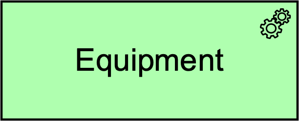
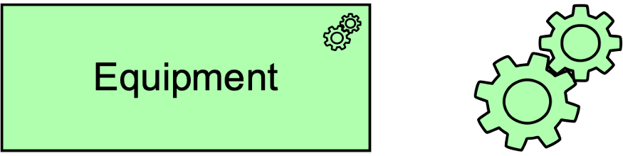
10.6.1. Equipment
Equipment represents one or more physical machines, tools, or instruments that can create, use, store, move, or transform materials.
Equipment comprises all active processing elements that carry out physical processes in which materials are used or transformed. It is possible to model nodes that are formed by a combination of IT infrastructure (devices, system software) and physical infrastructure (equipment); e.g., an MRI scanner at a hospital, a production plant with its control systems, etc.
Material can be accessed (e.g., created, used, moved, transformed, or otherwise manipulated) by equipment. Equipment may be assigned to material in order to model where the material is stored. Material may realize equipment. Equipment can serve other equipment as well as other active structure elements such as business roles and actors, and facilities can be assigned to equipment. A piece of equipment can be composed of other pieces of equipment or devices. Facilities can be assigned to equipment (i.e., equipment is installed and used in or on a facility). Equipment can be aggregated in a location.
The name of a piece of equipment should preferably be a noun.
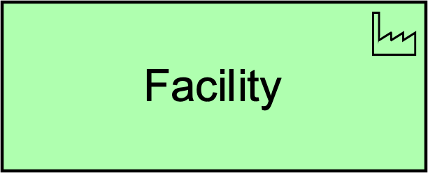
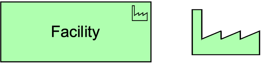
10.6.2. Facility
A facility represents a physical structure or environment.
A facility represents a physical resource that has the capability of facilitating (e.g., housing or locating) the use of equipment. It is typically used to model factories, buildings, or outdoor constructions that have an important role in production or distribution processes. Examples of facilities include a factory, laboratory, warehouse, shopping mall, cave, or spaceship. Facilities may be composite; i.e., consist of sub-facilities.
Facilities can be interconnected by distribution networks. A facility can serve other facilities and other active structure elements such as business roles and actors. A facility can be composed of other facilities or nodes and can be aggregated in a location.
The name of a facility should preferably be a noun referring to the type of facility; e.g., “Rotterdam oil refinery”.
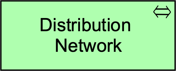
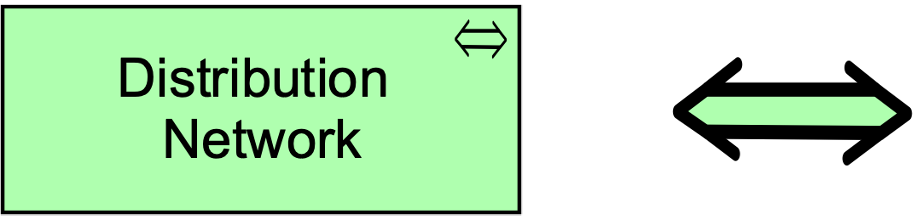
10.6.3. Distribution Network
A distribution network represents a physical network used to transport materials or energy.
A distribution network represents the physical distribution or transportation infrastructure. It embodies the physical realization of the logical paths between facilities.
A distribution network connects two or more facilities and may realize one or more paths. A distribution network can consist of sub-networks and can aggregate facilities and equipment to model railway stations and trains that are part of a rail network.
10.7. Passive Structure Elements
10.7.1. Material
Material represents tangible physical matter or energy.
Material is typically used to model raw materials and physical products, and also energy sources such as fuel and electricity. Material can be accessed by technology behavior elements to model how it is created, used, moved, transformed, or otherwise manipulated. Equipment may be assigned to material, to model where the material is stored. This allows you to model the distinction between, for instance, “the sand is in the dump truck” and “the sand is poured into the concrete mixer”. Material may realize equipment.
The name of material should be a noun. Pieces of material may be composed of other pieces of material.

10.8. Example
10.9. Summary of Technology Layer Elements
Table 8 gives an overview of the Technology Layer elements, with their definitions.
| Element | Definition | Notation | ||
|---|---|---|---|---|
Node |
Represents a computational or physical resource that hosts, manipulates, or interacts with other computational or physical resources. |
|
||
Device |
Represents a physical IT resource upon which system software and artifacts may be stored or deployed for execution. |
|
||
System Software |
Represents software that provides or contributes to an environment for storing, executing, and using software or data deployed within it. |
|
||
Technology Collaboration |
Represents an aggregate of two or more technology internal active structure elements that work together to perform collective technology behavior. |
|
||
Technology Interface |
Represents a point of access where technology services offered by a technology internal active structure can be accessed. |
|
||
Path |
Represents a link between two or more technology internal active structure elements, through which these elements can exchange data, energy, or material. |
|
||
Communication Network |
Represents a set of structures that connects devices or system software for transmission, routing, and reception of data. |
|
||
Technology Function |
Represents a collection of technology behavior that can be performed by a technology internal active structure element. |
|
||
Technology Process |
Represents a sequence of technology behaviors that achieves a specific result. |
|
||
Technology Interaction |
Represents a unit of collective technology behavior performed by (a collaboration of) two or more technology internal active structure elements. |
|
||
Technology Event |
Represents a technology state change. |
|
||
Technology Service |
Represents an explicitly defined exposed technology behavior. |
|
||
Artifact |
Represents a piece of data that is used or produced in a software development process, or by deployment and operation of an IT system. |
|
||
Equipment |
Represents one or more physical machines, tools, or instruments that can create, use, store, move, or transform materials. |
|
||
Facility |
Represents a physical structure or environment. |
|
||
Distribution Network |
Represents a physical network used to transport materials or energy. |
|
||
Material |
Represents tangible physical matter or energy. |
|