3. Language Structure
This chapter describes the structure of the ArchiMate Enterprise Architecture modeling language. The detailed definition and examples of its standard set of elements and relationships follow in Chapter 4 to Chapter 12.
3.1. Language Design Considerations
A key challenge in the development of a general metamodel for Enterprise Architecture is to strike a balance between the specificity of languages for individual architecture domains and a very general set of architecture concepts, which reflects a view of systems as a mere set of inter-related entities.
The design of the ArchiMate language started from a set of relatively generic concepts. These have been specialized towards application at different architectural layers, as explained in the following sections. The most important design restriction on the language is that it has been explicitly designed to be as small as possible, but still usable for most Enterprise Architecture modeling tasks. Many other languages try to accommodate the needs of all possible users. In the interest of simplicity of learning and use, the ArchiMate language has been limited to the concepts that suffice for modeling the proverbial 80% of practical cases.
3.2. Top-Level Language Structure
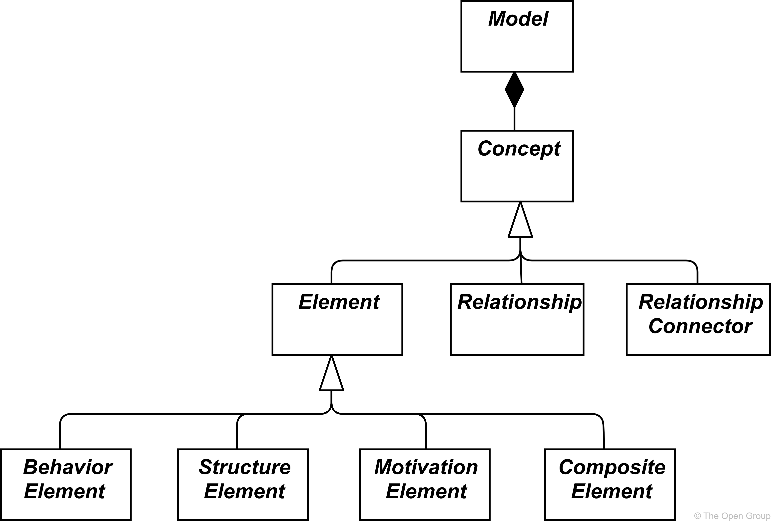
Figure 1 outlines the top-level hierarchical structure of the language:
-
A model is a collection of concepts – a concept is either an element or a relationship
-
An element is either a behavior element, a structure element, a motivation element, or a composite element
Note that these are abstract concepts; they are not intended to be used directly in models. To signify this, they are depicted in white with labels in italics. See Chapter 4 for an explanation of the notation used in Figure 1.

3.3. Layering of the ArchiMate Language
The ArchiMate core language defines a structure of generic elements and their relationships, which can be specialized in different layers. Three layers are defined within the ArchiMate core language as follows:
-
The Business Layer depicts business services offered to customers, which are realized in the organization by business processes performed by business actors.
-
The Application Layer depicts application services that support the business, and the applications that realize them.
-
The Technology Layer comprises both information and operational technology. You can model, for example, processing, storage, and communication technology in support of the application world and Business Layers, and model operational or physical technology with facilities, physical equipment, materials, and distribution networks.
The general structure of models within the different layers is similar. The same types of elements and relationships are used, although their exact nature and granularity differ. In the next chapter, the structure of the generic metamodel is presented. In Chapter 8, Chapter 9, and Chapter 10 these elements are specialized to obtain elements specific to a particular layer.
In alignment with service-orientation, the most important relationship between layers is formed by “serving”[1] relationships, which show how the elements in one layer are served by the services of other layers. (Note, however, that services need not only serve elements in another layer, but also can serve elements in the same layer.) A second type of link is formed by realization relationships: elements in lower layers may realize comparable elements in higher layers; e.g., a “data object” (Application Layer) may realize a “business object” (Business Layer); or an “artifact” (Technology Layer) may realize either a “data object” or an “application component” (Application Layer).
3.4. The ArchiMate Core Framework
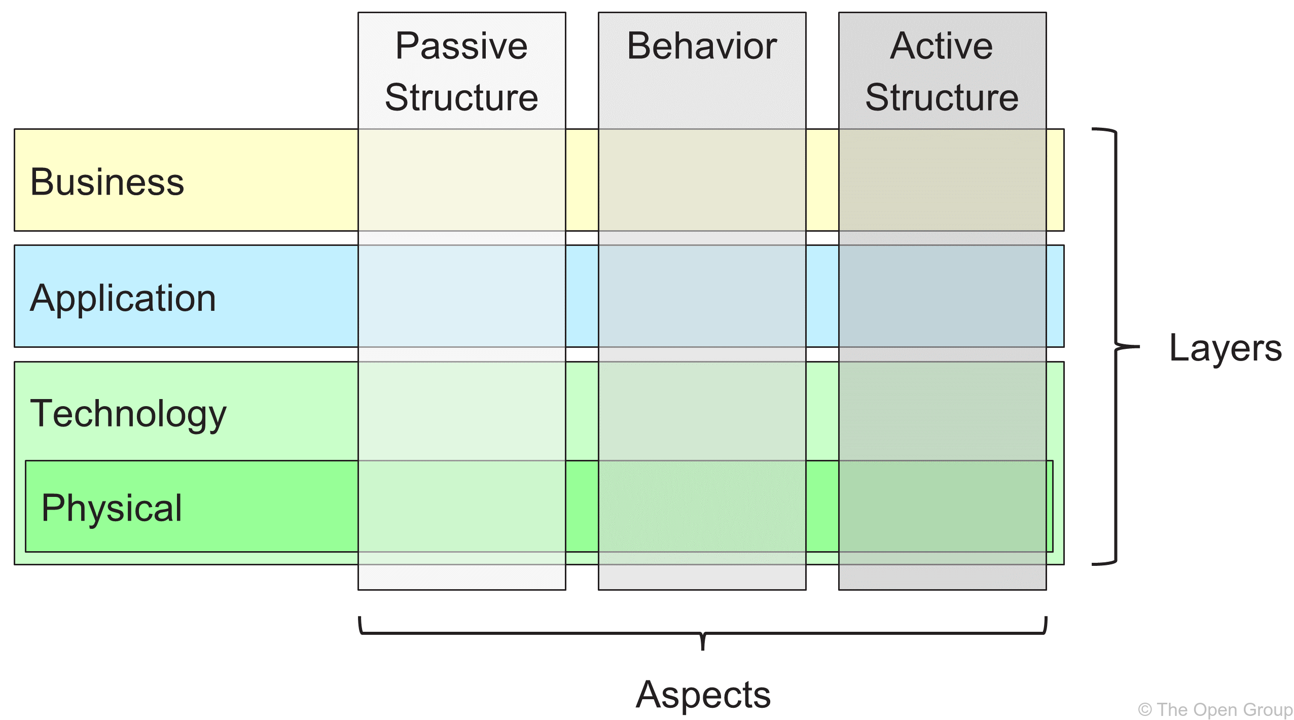
The ArchiMate Core Framework is a framework of nine cells used to classify elements of the ArchiMate core language. It is made up of three aspects and three layers, as illustrated in Figure 2. This is known as the ArchiMate Core Framework.
It is important to understand that the classification of elements based on aspects and layers is only a global one. Real-life architecture elements need not strictly be confined to one aspect or layer because elements that link the different aspects and layers, play a central role in a coherent architectural description. For example, running somewhat ahead of the later conceptual discussions, business roles serve as intermediary elements between “purely behavioral” elements and “purely structural” elements, and it may depend on the context whether a certain piece of software is considered to be part of the Application Layer or the Technology Layer.

The structure of the framework allows for modeling of the enterprise from different viewpoints, where the position within the cells highlights the concerns of the stakeholder. A stakeholder typically can have concerns that cover multiple cells.
The dimensions of the framework are as follows:
-
Layers – the three levels at which an enterprise can be modeled in ArchiMate – Business, Application, and Technology (as described in Section 3.3)
-
Aspects:
-
The Active Structure Aspect, which represents the structural elements (the business actors, application components, and devices that display actual behavior; i.e., the “subjects” of activity)
-
The Behavior Aspect, which represents the behavior (processes, functions, events, and services) performed by the actors; structural elements are assigned to behavioral elements, to show who or what displays the behavior
-
The Passive Structure Aspect, which represents the objects on which behavior is performed; these are usually information objects in the Business Layer and data objects in the Application Layer, but they may also be used to represent physical objects
These three aspects were inspired by natural language where a sentence has a subject (active structure), a verb (behavior), and an object (passive structure). By using the same constructs that people are used to in their own languages, the ArchiMate language is easier to learn and read.
Since ArchiMate notation is a graphical language where elements are organized spatially, this order is of no consequence in modeling.
-
A composite element, as shown in Figure 1, is an element that does not necessarily fit in a single aspect (column) of the framework but may combine two or more aspects.
Note that the ArchiMate language does not require the modeler to use any particular layout such as the structure of this framework; it is merely a categorization of the language elements.
3.5. The ArchiMate Full Framework
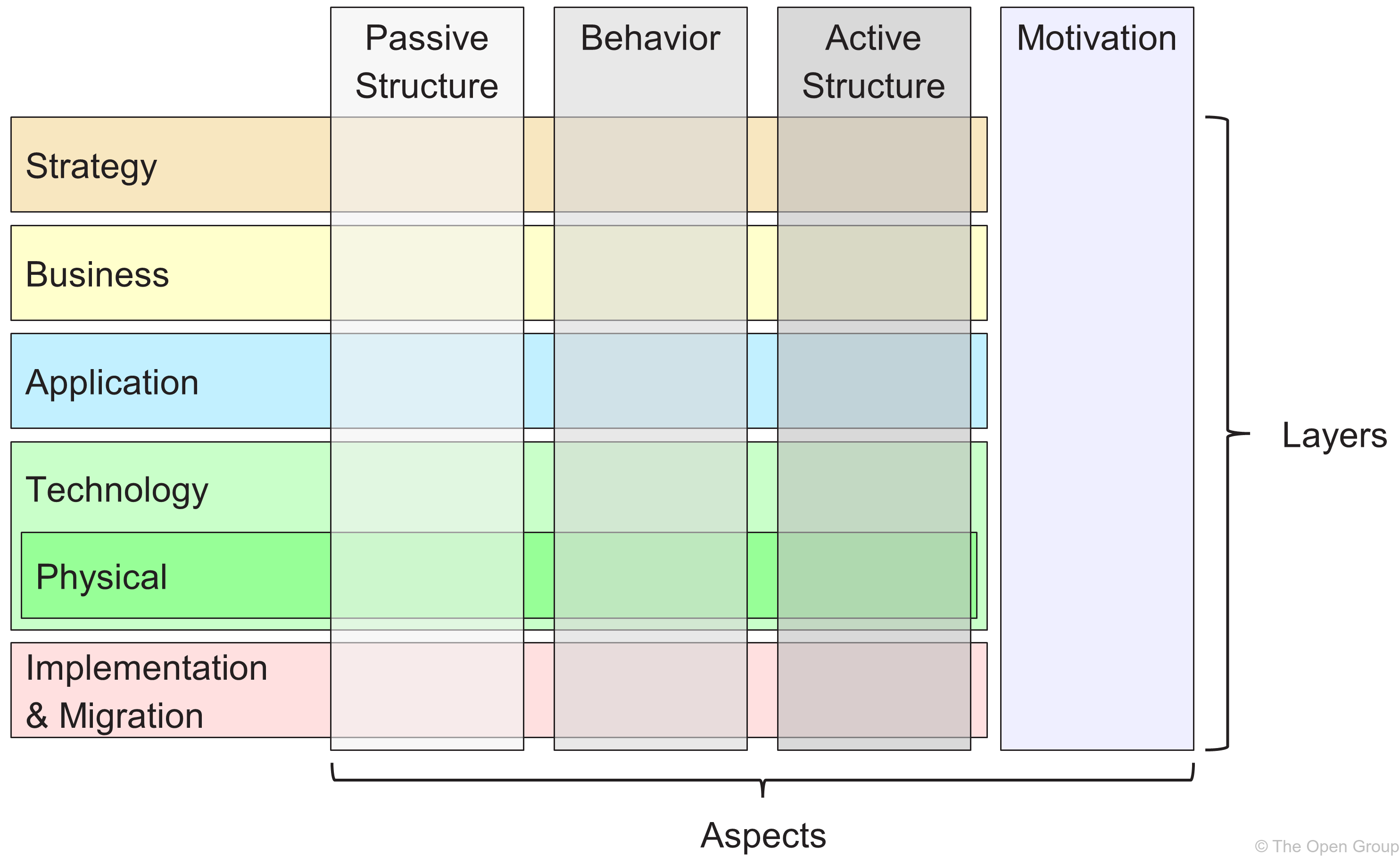
The ArchiMate Full Framework, as described in this version of the standard, adds a number of layers and an aspect to the Core Framework. The physical elements are included in the Technology Layer for modeling physical facilities and equipment, distribution networks, and materials. As such, these are also core elements. The strategy elements are introduced to model strategic direction and choices. They are described in Chapter 7. The motivation aspect is introduced at a generic level in the next chapter and described in detail in Chapter 6. The implementation and migration elements are described in Chapter 12. The resulting ArchiMate Full Framework is shown in Figure 3.

The ArchiMate language does not define a specific layer for information; however, elements from the passive structure aspect such as business objects, data objects, and artifacts are used to represent information entities. Information modeling is supported across the different ArchiMate layers.
3.6. Abstraction in the ArchiMate Language
The structure of the ArchiMate language accommodates several familiar forms of abstraction and refinement. First of all, the distinction between an external (black-box, abstracting from the contents of the box) and internal (white-box) view is common in systems design. The external view depicts what the system has to do for its environment, while the internal view depicts how it does this.
Second, the distinction between behavior and active structure is commonly used to separate what the system must do and how the system does it from the system constituents (people, applications, and infrastructure) that do it. In modeling new systems, it is often useful to start with the behaviors that the system must perform, while in modeling existing systems, it is often useful to start with the people, applications, and infrastructure that comprise the system, and then analyze in detail the behaviors performed by these active structures.
A third distinction is between conceptual, logical, and physical abstraction levels. This has its roots in data modeling: conceptual elements represent the information the business finds relevant; logical elements provide logical structure to this information for manipulation by information systems; physical elements describe the storage of this information; for example, in the form of files or database tables. In the ArchiMate language, this corresponds with business objects, data objects, and artifacts, along with the realization relationships between them.
The distinction between logical and physical elements has also been carried over to the description of applications. The TOGAF Enterprise Metamodel [4] includes a set of entities that describe business, data, application, and technology components and services to describe architecture concepts. Logical components are implementation or product-independent encapsulations of data or functionality, whereas physical components are tangible software components, devices, etc. This distinction is captured in the TOGAF framework in the form of Architecture Building Blocks (ABBs) and Solution Building Blocks (SBBs). This distinction is again useful in progressing Enterprise Architectures from high-level, abstract descriptions to tangible, implementation-level designs. Note that building blocks may contain multiple elements, which are typically modeled using the grouping concept in the ArchiMate language.
The ArchiMate language has three ways of modeling such abstractions. First, as described in [6], behavior elements such as application and technology functions can be used to model logical components, since they represent implementation-independent encapsulations of functionality. The corresponding physical components can then be modeled using active structure elements such as application components and nodes, assigned to the behavior elements. Second, the ArchiMate language supports the concept of realization. This can best be described by working with the Technology Layer upwards. The Technology Layer defines the physical artifacts and software that realize an application component. It also provides a mapping to other physical concepts such as devices, networks, etc. needed for the realization of an information system. The realization relationship is also used to model more abstract kinds of realization, such as that between a (more specific) requirement and a (more generic) principle, where fulfillment of the requirement implies adherence to the principle. Realization is also allowed between application components and between nodes. This way you can model a physical application or technology component realizing a logical application or technology component, respectively. Third, logical and physical application components can be defined as metamodel-level specializations of the application component element, as described in Chapter 14 (see also the examples in Section 14.2.2). The same holds for the logical and physical technology components of the TOGAF Content Metamodel, which can be defined as specializations of the node element (see Section 14.2.3).
The ArchiMate language intentionally does not support a difference between types and instances. At the Enterprise Architecture abstraction level, it is more common to model types and/or exemplars rather than instances. Similarly, a business process in the ArchiMate language does not describe an individual instance (i.e., one execution of that process). In most cases, a business object is therefore used to model an object type (cf. a UML®) class), of which several instances may exist within the organization. For instance, each execution of an insurance application process may result in a specific instance of the insurance policy business object, but that is not modeled in the Enterprise Architecture.
3.7. Concepts and their Notation
The ArchiMate language separates the language concepts (i.e., the constituents of the metamodel) from their notation. Different stakeholder groups may require different notations in order to understand an architecture model or view. In this respect, the ArchiMate language differs from languages such as UML or BPMN™, which have only one standardized notation. The viewpoint mechanism explained in Chapter 13 provides the means for defining such stakeholder-oriented visualizations.
Although the notation of the ArchiMate concepts can (and should) be stakeholder-specific, the standard provides one common graphical notation which can be used by architects and others who develop ArchiMate models. This notation is targeted towards an audience used to existing technical modeling techniques such as Entity Relationship Diagrams (ERDs), UML, or BPMN, and therefore resembles them. In the remainder of this document, unless otherwise noted, the symbols used to depict the language concepts represent the ArchiMate standard notation. This standard notation for most elements consists of a box with an icon in the upper-right corner. In several cases, this icon by itself may also be used as an alternative notation. This standard iconography should be preferred whenever possible so that anyone knowing the ArchiMate language can read the diagrams produced in the language.
3.8. Use of Nesting
Nesting elements inside other elements can be used as an alternative graphical notation to express some relationships. This is explained in more detail in Chapter 5 and in the definition of each of these relationships.
3.9. Use of Colors and Notational Cues
In the metamodel pictures within this standard, shades of grey are used to distinguish elements belonging to the different aspects of the ArchiMate framework, as follows:
-
White for abstract (i.e., non-instantiable) concepts
-
Light grey for passive structures
-
Medium grey for behavior
-
Dark grey for active structures
In ArchiMate models, there are no formal semantics assigned to colors and the use of color is left to the modeler. However, they can be used freely to stress certain aspects in models. For instance, in many of the example models presented in this standard, colors are used to distinguish between the layers of the ArchiMate Core Framework, as follows:
-
Yellow for the Business Layer
-
Blue for the Application Layer
-
Green for the Technology Layer
They can also be used for visual emphasis; see Chapter 6 in [1]. In addition to the colors, other notational cues can be used to distinguish between the layers of the framework. A letter M, S, B, A, T, P, or I in the top-left corner of an element can be used to denote a Motivation, Strategy, Business, Application, Technology, Physical, or Implementation & Migration element, respectively. An example of this notation is depicted in Example 34.
The standard notation also uses a convention with the shape of the corners of its symbols for different element types, as follows:
-
Square corners are used to denote structure elements
-
Round corners are used to denote behavior elements
-
Diagonal corners are used to denote motivation elements